RojoPony
Just got it firing!
- Joined
- Mar 7, 2010
- Messages
- 7
As fall changed into winter I still had the desire to go riding but was finding that the hands were getting too unbearably cold while the rest of me was coping with the temperature drop. I had read from several sources that the Breva 1100 had factory heated grips available, but I found the price to be a bit more than I desired to pay. My frugality lead me to look further into adding heat to the grips of the B1100 at a price I was willing to dole out. I finally settled on trying Hot Grips 475-876 grips that I found at $109 at Dennis Kirk. During my investigations I had read at a couple of sites that any brand of heated grips should be able to be wired into the Breva's built-in wiring harness with the addition of a momentary switch to control the operation.
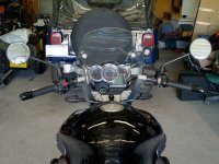
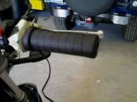
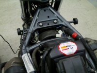
Here is the starting point of the installation with the stock grips in place.
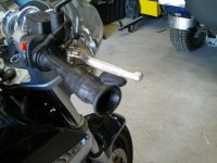
To start the first thing is to remove the bar end weights. Now to remove the stock grips, I started on the left (clutch) side of the bike. I inserted an air blow gun attached to a compressor to blow compressed air between the grip and the bar which allowed the grip to easily slip off the bar. The right grip was a bit harder to get off due to the internal ribs between the grip and throttle sleeve. I used the compressed air to loosen the grip but could not pull it off, so instead I sprayed the grip with soapy water, inverted the grip over itself and pulled it off that way.
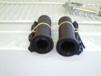
Now if you look at the ends of the new Hot Grips you will notice that they have different inside diameters. The small diameter goes on the left side and the larger diameter goes on the right side of the handlebars.
I found that the left grip slide on and off the bar with only a bit of friction, which was going to be good when it came time to epoxy the grip in place. Also the left grip slide on the bar far enough that it did not interfere with the bar end weight.
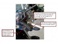
The right grip I found would take a bit of work to get the grip to fit onto the throttle sleeve. First, around the circumference of the end of the throttle sleeve was a series of ridges, I used a pair of flush cutters to clip these ridges off. Next obstacle to sliding the grip on was a series of “H” shaped formations that ran along both slides of the sleeve, these “H”s were easily dispatched with the flush cutters. Now the grip will slide onto the throttle sleeve, but alas the last problem cropped up when I notice that the end of the grip did not clear the end of the bar. The stock grip form fits over the beveled flange at the inner end of the throttle sleeve. I placed some masking tape on the throttle control and proceeded to attack the bevel with a Dremmel tool with a grinder bit and a file to grind the bottom of the bevel off enough to allow the grip to clear the bar end and not interfere with the bar end weight. The instructions with the Hot Grips recommends filing off all ridges on the throttle sleeve, but I found that the grip fit very well and the ridges served as great key ways that would later assist in line up of installation of the grip and reduce the amount of epoxy that would be required to hold the grip in place.
Now that the grips will go on the bars I now looked at positioning the grips so the wires coming off the grips would line up well with existing wiring and on the throttle side move in a manner that would not interfere with throttle or brake leaver operation. Pretty much on each side the wiring points down and slightly towards the front of the bike.
I marked the positions on the end of the bars and end of the grips for reference for when the epoxy was to be laid on. The Hot Grip instructions says to use a 2 part epoxy to glue the grips onto the bars that can endure temperatures of at least 250 degrees, which negates using any quick set epoxy. I mixed a pool of epoxy up and then ran a line approximately 3/8th to ½ in wide on both side of the bar before sliding the grips onto the bars. The instructions with the kit recommend wiring up the grips and running them at half power for 20 minutes to quicken the epoxy setting and have the setting occur when the grips are expanded the most. I wired the rig up to a battery from an ATV I had lying about and used that for powering the grips for the 20 minutes. Heating the grips I found had another advantage in that I know for sure that the grips actually work before the epoxy fully hardened.
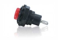
Now comes the installation of the control switch into the Breva's instrument panel. I wanted to install the switch in the stock location so I went to Radio Shack and looked over the selection of momentary switches they had in stock and settled on part number 275-646.
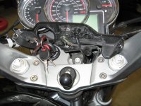
I removed the two screws that hold the switch panel to the dash of the bike and rotated and lifted the panel up to expose the bottom. The button blank I desired to use was removed by pushing it though the control panel after removing two screws that hold a small blocker panel in place which prevents the buttons from being pushed out of the control panel.
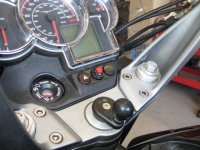
After getting the button blank I wanted to install my switch in, I saw a small problem in that the blank had a inner diameter too small to allow me to put the button in and then secure it in place with the nut that came with it. An idea came to me that might allow me to use the switch I had in the blank I wanted to use. I took the blank over to the drill press and drilled out a 31/64th in. hole into the blank and then pressed the switch into the blank. The 31/64th in. hole is slightly smaller than the ½ in. diameter hole the switch was designed for and the friction of the switch threads against the small hole is enough to firmly hold the switch in place. A quick test fit of the blank into the dash then presented me with another problem in that the switch terminals now will not clear the button securing bracket. Once again a little head scratching ensued and another workaround was found. Using a sanding block, I sanded the teeth off of the plastic nut that came with the switch to make it where it would lie flush against a flat surface. I removed the switch from the switch blank, screwed the nut onto the switch and then inserted the switch back into the blank. The added thickness of the nut raised the terminals of the switch a sufficient amount to clear the switch panel backing plate. Before final reassembly of the dash panel, I soldered one of the kit's approximately 3 ft. length of wire to the switch and routed it into the handlebar assembly along the same route as stock wiring.
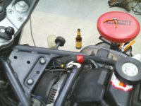
Now the final wiring into the Breva's stock wiring harness was to begin. The stock heated grip wiring is located under the fuel tank near the right frame rail. The wiring harness location required the removal of the gas tank. If you have never removed the tank there are instructions in several Guzzi centric forums. The biggest pain to tank removal is figuring out the fuel line quick connect for the first time, I've found that after the first disconnect of the fuel line future removal is much easier. The connections for the heated grips are tied together, you will see two connections that have blue wires and a third connector with brown wire. The blue wire connections are the connections that will be connected to the hand grips and the brown connection will be for the switch added to the dash board.
Run the wires from grips and the dashboard down along the same pathways as other control wires from these locations down to the connectors. Zip tie the wires as needed along the way to prevent them from getting tangled in things they don't need to get tangled into or rubbed against. I did not have any connectors that would work with the factory connections, so I elected to clip the connectors off and solder all wires directly together. When soldering the wires, you don't need to worry about polarity between the wires from the grips and switch to their connectors in the factory wiring harness. Once you have all wires soldered, wrap them in electrical tape or shrink tubing and then zip tie them so they don't move about.
Now you can put the tank back onto the bike and button up any other parts of the bike you have disassembled. To test out the grips start the bike and press the button on the dash panel for a couple of seconds, you should now see the heated grip display appear on the Breva's dash board. Once you have the grip operation showing on the dash board, let the bike run for a few minutes then check the grips to see if they are heating up. In normal operation quick presses of the button will change the heat levels and another long press will shut the grips off. The bike will also remember the last setting of the grips when the bike was shutdown and will set the grips to that setting when started again.
So far I've been very satisfied with the performance of these grips. I've found that so far I mostly run them on medium and only turn them up to high when riding at highway (70mph+) speeds with temperatures below 50f. Another thing that I really like about these grips is that they are a larger diameter than the stock grips which my hands find to be much more comfortable.
Here is the starting point of the installation with the stock grips in place.
To start the first thing is to remove the bar end weights. Now to remove the stock grips, I started on the left (clutch) side of the bike. I inserted an air blow gun attached to a compressor to blow compressed air between the grip and the bar which allowed the grip to easily slip off the bar. The right grip was a bit harder to get off due to the internal ribs between the grip and throttle sleeve. I used the compressed air to loosen the grip but could not pull it off, so instead I sprayed the grip with soapy water, inverted the grip over itself and pulled it off that way.
Now if you look at the ends of the new Hot Grips you will notice that they have different inside diameters. The small diameter goes on the left side and the larger diameter goes on the right side of the handlebars.
I found that the left grip slide on and off the bar with only a bit of friction, which was going to be good when it came time to epoxy the grip in place. Also the left grip slide on the bar far enough that it did not interfere with the bar end weight.
The right grip I found would take a bit of work to get the grip to fit onto the throttle sleeve. First, around the circumference of the end of the throttle sleeve was a series of ridges, I used a pair of flush cutters to clip these ridges off. Next obstacle to sliding the grip on was a series of “H” shaped formations that ran along both slides of the sleeve, these “H”s were easily dispatched with the flush cutters. Now the grip will slide onto the throttle sleeve, but alas the last problem cropped up when I notice that the end of the grip did not clear the end of the bar. The stock grip form fits over the beveled flange at the inner end of the throttle sleeve. I placed some masking tape on the throttle control and proceeded to attack the bevel with a Dremmel tool with a grinder bit and a file to grind the bottom of the bevel off enough to allow the grip to clear the bar end and not interfere with the bar end weight. The instructions with the Hot Grips recommends filing off all ridges on the throttle sleeve, but I found that the grip fit very well and the ridges served as great key ways that would later assist in line up of installation of the grip and reduce the amount of epoxy that would be required to hold the grip in place.
Now that the grips will go on the bars I now looked at positioning the grips so the wires coming off the grips would line up well with existing wiring and on the throttle side move in a manner that would not interfere with throttle or brake leaver operation. Pretty much on each side the wiring points down and slightly towards the front of the bike.
I marked the positions on the end of the bars and end of the grips for reference for when the epoxy was to be laid on. The Hot Grip instructions says to use a 2 part epoxy to glue the grips onto the bars that can endure temperatures of at least 250 degrees, which negates using any quick set epoxy. I mixed a pool of epoxy up and then ran a line approximately 3/8th to ½ in wide on both side of the bar before sliding the grips onto the bars. The instructions with the kit recommend wiring up the grips and running them at half power for 20 minutes to quicken the epoxy setting and have the setting occur when the grips are expanded the most. I wired the rig up to a battery from an ATV I had lying about and used that for powering the grips for the 20 minutes. Heating the grips I found had another advantage in that I know for sure that the grips actually work before the epoxy fully hardened.
Now comes the installation of the control switch into the Breva's instrument panel. I wanted to install the switch in the stock location so I went to Radio Shack and looked over the selection of momentary switches they had in stock and settled on part number 275-646.
I removed the two screws that hold the switch panel to the dash of the bike and rotated and lifted the panel up to expose the bottom. The button blank I desired to use was removed by pushing it though the control panel after removing two screws that hold a small blocker panel in place which prevents the buttons from being pushed out of the control panel.
After getting the button blank I wanted to install my switch in, I saw a small problem in that the blank had a inner diameter too small to allow me to put the button in and then secure it in place with the nut that came with it. An idea came to me that might allow me to use the switch I had in the blank I wanted to use. I took the blank over to the drill press and drilled out a 31/64th in. hole into the blank and then pressed the switch into the blank. The 31/64th in. hole is slightly smaller than the ½ in. diameter hole the switch was designed for and the friction of the switch threads against the small hole is enough to firmly hold the switch in place. A quick test fit of the blank into the dash then presented me with another problem in that the switch terminals now will not clear the button securing bracket. Once again a little head scratching ensued and another workaround was found. Using a sanding block, I sanded the teeth off of the plastic nut that came with the switch to make it where it would lie flush against a flat surface. I removed the switch from the switch blank, screwed the nut onto the switch and then inserted the switch back into the blank. The added thickness of the nut raised the terminals of the switch a sufficient amount to clear the switch panel backing plate. Before final reassembly of the dash panel, I soldered one of the kit's approximately 3 ft. length of wire to the switch and routed it into the handlebar assembly along the same route as stock wiring.
Now the final wiring into the Breva's stock wiring harness was to begin. The stock heated grip wiring is located under the fuel tank near the right frame rail. The wiring harness location required the removal of the gas tank. If you have never removed the tank there are instructions in several Guzzi centric forums. The biggest pain to tank removal is figuring out the fuel line quick connect for the first time, I've found that after the first disconnect of the fuel line future removal is much easier. The connections for the heated grips are tied together, you will see two connections that have blue wires and a third connector with brown wire. The blue wire connections are the connections that will be connected to the hand grips and the brown connection will be for the switch added to the dash board.
Run the wires from grips and the dashboard down along the same pathways as other control wires from these locations down to the connectors. Zip tie the wires as needed along the way to prevent them from getting tangled in things they don't need to get tangled into or rubbed against. I did not have any connectors that would work with the factory connections, so I elected to clip the connectors off and solder all wires directly together. When soldering the wires, you don't need to worry about polarity between the wires from the grips and switch to their connectors in the factory wiring harness. Once you have all wires soldered, wrap them in electrical tape or shrink tubing and then zip tie them so they don't move about.
Now you can put the tank back onto the bike and button up any other parts of the bike you have disassembled. To test out the grips start the bike and press the button on the dash panel for a couple of seconds, you should now see the heated grip display appear on the Breva's dash board. Once you have the grip operation showing on the dash board, let the bike run for a few minutes then check the grips to see if they are heating up. In normal operation quick presses of the button will change the heat levels and another long press will shut the grips off. The bike will also remember the last setting of the grips when the bike was shutdown and will set the grips to that setting when started again.
So far I've been very satisfied with the performance of these grips. I've found that so far I mostly run them on medium and only turn them up to high when riding at highway (70mph+) speeds with temperatures below 50f. Another thing that I really like about these grips is that they are a larger diameter than the stock grips which my hands find to be much more comfortable.
Attachments
-
 1 Before Shot.JPG136.7 KB · Views: 857
 -
 2 Invert Throttle Grip.JPG106.7 KB · Views: 856
 -
 4 New Grips.JPG72.5 KB · Views: 855
 -
 3a Throttle Grip Removed - Annotated.JPG.jpg70.3 KB · Views: 859
 -
 6 Throttle Trial Fit.JPG120.4 KB · Views: 856
 -
 8a Shack Switch.JPG4.5 KB · Views: 689
 -
 8 Switch Placement.JPG175.4 KB · Views: 859
 -
 9 Switch In Place.JPG172.6 KB · Views: 857
 -
 10 Stock Wires.JPG112.4 KB · Views: 859
 -
 11 Grips & Switch Wired In.JPG118.9 KB · Views: 858