• Ciao Guest - You’ve landed at the ultimate Guzzi site. NEW FORUM REGISTRATIONS REQUIRE EMAIL ACTIVATION - CHECK YOUR SPAM FOLDER - Use the CONTACT above if you need help. New to the forum? For all new members, we require ONE post in the Introductions section at the bottom, in order to post in most of the other sections. ALWAYS TRY A SEARCH BEFORE STARTING A NEW TOPIC - Most questions you may have, have likely been already answered. DON'T BE A DRIVE-BY POSTER: As a common courtesy, check back in and reply within 24 hours, or your post will be deleted. Note there's decades of heavily experienced Guzzi professionals on this site, all whom happily give endless amounts of their VALUABLE time for free; BE COURTEOUS AND RESPECTFUL!
  • There is ZERO tolerance on personal attacks and ANY HYPERLINKS to PRODUCT(S) or other competing website(s), including personal pages, social media or other Forums. This ALSO INCLUDES ECU DIAGnostic software, questions and mapping. We work very hard to offer commercially supported products and to keep info relevant here. First offense is a note, second is a warning, third time will get you banned from the site. We don't have the time to chase repeat (and ignorant) offenders. This is NOT a social media platform; It's an ad-free, privately funded website, in small help with user donations. Be sure to see the GTM STORE link above; ALL product purchases help support the site, or you can upgrade your Forum profile or DONATE via the link above.
  • Be sure to see the GTM STORE link also above for our 700+ product inventory, including OEM parts and many of our 100% Made-in-SoCal-USA GTM products and engine kits. In SoCal? Click the SERVICE tab above for the best in service, tires, tuning and installation of our products or custom work, and don't miss our GT MotoCycles® (not) art on the BUILDS tab above. WE'RE HERE ONLINE ONLY - NO PHONE CALLS MADE OR RECEIVED - DO NOT EMAIL AND ASK QUESTIONS OR ASK TO CALL YOU.
  • Like the new V100, GuzziTech is full throttle into the future! We're now running on an all-new server and we've updated our Forum software. The visual differences are obvious, but hopefully you'll notice the super-fast speed. If you notice any glitches or have any issues, please post on the Site Support section at the bottom. If you haven't yet, please upgrade your account which is covered in the Site Support section or via the DONATE tab above, which gives you full site access including the DOWNLOADS section. We really appreciate every $ and your support to keep this site ad-free. Create an account, sign in, upgrade your account, and enjoy. See you on the road in 2024.

Rollerization

Got my Stelvio back yesterday from its "rollerization" adventure. Three months almost to the day from when I took it in.

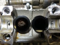
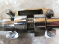
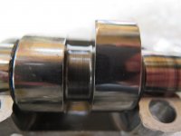
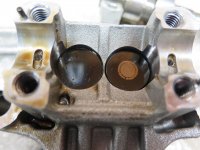
Took it to "Scoot Richmond" in Richmond, VA. This is the first Stelvio (I think) that they have done. My 2009 had 39,000 miles on it, and so far had shown no signs of increasing valve clearance. They took out the tappets and found discoloration of the surface but no material loss, so I timed THAT just right.

Since it's a 2009, it needed the "C" kit, and Piaggio (as usual) wanted lots of documentation, the original warranty book, photos, etc, which took a couple of months for them to analyze once we sent it. (As a side note, Piaggio's attitude torqued my wife and I off so bad that we bought a new Triumph Trophy SE triple while we were in there.) The shop finally received the kit, installed it, did the centerstand recall, loaded the latest map, and generally did an excellent job for under $900 labor.

I rode it 100 miles home yesterday, and it's running better than ever - the cyclic "clatter" from the rocker arms has gone away now. So I may keep the Stelvio along with the Triumph if it behaves well .... and I can recommend "Scoot Richmond" for anyone that needs this kind of work.

Lannis

Good news and good news to know re that dealer.

FWIW, Winchester Motosports has just done its first roller job and appears to have gone well. Mike is a gifted Guzzi wrench. He even came out to the house recently (with Carl's blessings "on the meter") to help me with a task or two on my Norge ... which stills sits in a state of advanced deshabille on my lift ... tho comes off soon! :wasntme:

The real moral of your story is not to annoy your bride, tho I cannot help but wonder if that was not intentionally and quite deftly done on your part. If so, well done, Sir; well done. ;)

Bill
 
center stand recall is interesting. 2 years ago they swore it didn't exist even after I produced the # or a copy of it.
Wayne was kind enough to weld mine up with some supports and it worked fine until I sold it.
 
Well, I wasn't too keen on doing this but the thought of little bits of metal flailing about in my engine and it slowly grinding itself apart I went ahead and did the rollerization to my 2012 Norge. Parts were $1,019 from AF1 with under 1 week delivery. It was the "A" kit so no head removal. I already had the fuel tank off to do the tappets so I decided to just jump in. While I proceeded slowly and double checked everything (except probably something I forgot) it went smoothly. Using the slip the long straight screwdriver trick down the left side worked fine and I used an old allen wrench that just barely fit in the bolt hole to hold the tensioner back making sure it was straight when I removed the screwdriver. The chain and gear slipped right back on the new cam easily. I never removed the gear from the chain and made sure the pin on the cam was in the same position so the timing remained the same. For the right side I removed the rear mount from the air box and picked up the front and was able to reach the cap for the right side timing chain tensioner without airbox removal. You will need a 36mm socket and probably a breaker bar as it is way too tight. I was lucky as the special 36mm low profile socket I need to change oil on my Mini Cooper worked perfect. I fired it up last night and using the new 0.004" and 0.006" tappet settings I was amazed how much quieter the engine was. It has only ran about a minute on the rebuild so I need to complete the reassembly and get a test ride in before I can announce I did it without grenading the engine. Overall I didn't think it was too bad of a job. I did cheat and flexed my fairing to remove the cam boxes instead of removing it. I have to look but I think removing a couple of lower fairing mounting screws probably would have been a better idea so it flexed over a larger area. I was lucky as in my garage the lift sits in front of the heater and the plastic was fairly warm due to our cold weather and the heater running so much. With 2,900 miles it showed some wear already.
 

Attachments

  • 2016-04-02 Roller lifter kit left 05.JPG
    2016-04-02 Roller lifter kit left 05.JPG
    171.4 KB · Views: 58
  • 2016-04-02 Roller lifter kit left 06.JPG
    2016-04-02 Roller lifter kit left 06.JPG
    64.7 KB · Views: 55
  • 2016-04-02 Roller lifter kit right 12.JPG
    2016-04-02 Roller lifter kit right 12.JPG
    67.8 KB · Views: 55
  • 2016-04-02 Roller lifter right  kit 11.JPG
    2016-04-02 Roller lifter right kit 11.JPG
    130.7 KB · Views: 58
did mine today, or at ;least took the old cam boxes out - both sides worn, left mpore so. just need to spend the money now
 
did mine today, or at ;least took the old cam boxes out - both sides worn, left mpore so. just need to spend the money now


I hope you didn't remove both at the same time. Turning the engine with one of the cam chains off may impact the cam timing. Be sure to verify cam timing on assembly.
 
I am afraid i did take both off, but i ensured that the sprocket didnt move on the chain by zip tying it up after setting the 'nipple hole' to six clock bothe sides before removbing the boxes. However, now that everything is back together again i tried to start it up (having fitst pulled the plugs and turned it over a few times) but it wont start, doesnt even try to

Battery is fine, fuel pump primes, plugs are wet and getting a spark but no start ?
 
As long as the chains did not jump a tooth and you put the pin back on the correct L an R hole on the respective cam (L and R as u sit on the bike) then you will be fine with timing.

Did u reset your valves again. You have to after the boxes have been off. If the plugs are wet sounds like you are not getting compression. I would confirm the proper gaps and for safe measure confirm the right L and R hole on the cam. At the respective TDC for each side the pin and hole should be at 6 o'clock Start easy.
 
The nipple is in the correct hole each side, the marking was very clear so easily identified.

I did reset the valves. I will get the coivers off and check them wgain and the sprockets
 
Just because the cam pin is in the correct hole, it doesn't mean it is correct position in relation to the crank shaft. Each cylinder on compression the cam pin should be at about the 6 o'clock position relative to the crank shaft. My fear is that the chain moved on the lower sprockets. The service manual sort of gives you a procedure to set the valve timing. See the section of fitting the cylinder head. That is best description of crank to camshaft position that I could find..
 
John if u read my post I already covered the 6 o'clock position with him at TDC. Think he is now checking that to make sure the timing is correct.
 
John if u read my post I already covered the 6 o'clock position with him at TDC. Think he is now checking that to make sure the timing is correct.


Yes read that. Just trying to re-enforce after what jim wrote. Being in the correct hole in the sprocket isn't enough for the timing to be right. That is also why I referenced the service manual. It gives a little more detail. I just set the cam timing on a Daytona engine a few weeks ago. Getting the in head cams correct just isn't as simple as getting the cam timing correct on a 2 valve engine. Much more to consider.
 
Yes read that. Just trying to re-enforce after what jim wrote. Being in the correct hole in the sprocket isn't enough for the timing to be right. That is also why I referenced the service manual. It gives a little more detail. I just set the cam timing on a Daytona engine a few weeks ago. Getting the in head cams correct just isn't as simple as getting the cam timing correct on a 2 valve engine. Much more to consider.

What is correct valve clearance gap. I have used 15mm in and 20 out as manual states but is it different for when rollers are fitted ?
 
Assuming u mean 0.15 and 0.20mm. That will work as will 0.10 and 0.15mm. I read your post on WG. What valve rubber seal are u referring to that blew off.

Did u verify that the timing is correct at each TDC. Each cylinder must be at its own TDC on compression to check valves and the position of the pins.

As John has stated you most likely jumped some teeth on the crank. You need to verify that before you do anything else and before we can help more. If the timing is off does not matter what else u do. It will not fire.
 
Actually there is a shaft, driven by the crank that resides where a camshaft once was. There are two sprockets on this shaft that drive the individual chains. It appears that you can get enough slack in the chain for it to move position on these shaft sprockets (see item 1 below). Again the factory manual does give you a procedure to set the cam timing.

Upload 2016 5 8 7 33 52
 
Sounds like it is getting too techie for me. I don't know how to verify if the chain has jumped teeth on crank.

The little valve is on the manifold inlet each side. Has a hard rubber cover. The left one blew off when I cranked the engine last time.

I have a copy of the service manual but it has nothing I an find that is of help, only reference to valve clearances is on page 65 and cmshaft on 194,your diagram is on 195.
 
Last edited:
What bike are we referring to and what year........

No rubber covers that come to mind on the throttle bodies (assuming that is what you are referring to). A picture of the caps would help.

Are they small rubber caps about 3/16" in diameter. If so, sounds like they are caps to cover the connections where the canister used to hook up for vacuum. Someone may have disconnected the canister and put caps on to use them as balancing ports. If that is the case and they are blowing off that means your timing is probably off and you are getting compression back through the tb's. That would mean that the left side could be out of timing by 180 degrees. Sounds like you are on the exhaust or compression stroke and the inlet valves are opening.

Are you sure you set each cylinder TDC separately when you re-assembled the respective side.

Did you verify the position of the pins at the individual cylinders TDC. We can do all the speculating in the world on timing and probably causes. If they are off then you can fix the timing. As John said there is a procedure to fix the timing by hate for you to go through the procedure only to find that the timing was not off. Although, all the evidence is pointing that way.

It sounds like the little valve is what you describe.

To the best of my memory, which is now getting confused I did each side separately, starting on right side

I verified the position of the pins on both sides
 
Go to the section on installing cylinder head. On my US version it is Engine page 154. Start there, read it though and see if it makes sense to you.
 
I saw your pic on WG. That is what it is. That means you are getting pressure back through the TB.

U verified the pin position at each separate TDC on each side at the compression stroke.

John. If the timing my is out by 180 will the pin still be in the same spot at TDC I think I answered my own question at no but something is not making sense here. Unless he bent an inlet valve
 
Back
Top