• Ciao Guest - You’ve landed at the ultimate Guzzi site. NEW FORUM REGISTRATIONS REQUIRE EMAIL ACTIVATION - CHECK YOUR SPAM FOLDER - Use the CONTACT above if you need help. New to the forum? For all new members, we require ONE post in the Introductions section at the bottom, in order to post in most of the other sections. ALWAYS TRY A SEARCH BEFORE STARTING A NEW TOPIC - Most questions you may have, have likely been already answered. DON'T BE A DRIVE-BY POSTER: As a common courtesy, check back in and reply within 24 hours, or your post will be deleted. Note there's decades of heavily experienced Guzzi professionals on this site, all whom happily give endless amounts of their VALUABLE time for free; BE COURTEOUS AND RESPECTFUL!
  • There is ZERO tolerance on personal attacks and ANY HYPERLINKS to PRODUCT(S) or other competing website(s), including personal pages, social media or other Forums. This ALSO INCLUDES ECU DIAGnostic software, questions and mapping. We work very hard to offer commercially supported products and to keep info relevant here. First offense is a note, second is a warning, third time will get you banned from the site. We don't have the time to chase repeat (and ignorant) offenders. This is NOT a social media platform; It's an ad-free, privately funded website, in small help with user donations. Be sure to see the GTM STORE link above; ALL product purchases help support the site, or you can upgrade your Forum profile or DONATE via the link above.
  • Be sure to see the GTM STORE link also above for our 700+ product inventory, including OEM parts and many of our 100% Made-in-SoCal-USA GTM products and engine kits. In SoCal? Click the SERVICE tab above for the best in service, tires, tuning and installation of our products or custom work, and don't miss our GT MotoCycles® (not) art on the BUILDS tab above. WE'RE HERE ONLINE ONLY - NO PHONE CALLS MADE OR RECEIVED - DO NOT EMAIL AND ASK QUESTIONS OR ASK TO CALL YOU.
  • Like the new V100, GuzziTech is full throttle into the future! We're now running on an all-new server and we've updated our Forum software. The visual differences are obvious, but hopefully you'll notice the super-fast speed. If you notice any glitches or have any issues, please post on the Site Support section at the bottom. If you haven't yet, please upgrade your account which is covered in the Site Support section or via the DONATE tab above, which gives you full site access including the DOWNLOADS section. We really appreciate every $ and your support to keep this site ad-free. Create an account, sign in, upgrade your account, and enjoy. See you on the road in 2024.

Rostra Cruise Control Installation on '12 NTX

ChuckH

Tuned and Synch'ed
Joined
Sep 3, 2011
Messages
78
Location
Columbus, IN
OK, I'm getting close to finishing the installation of a Rostra Electronic Cruise Control on my 2012 NTX. This unit was on my Wee-Strom and I am now moving it over to the new bike. The installation has not been difficult but the installation options are very limited. The Guzzi engineers did a good job of packaging this bike so there are not many extra nooks and crannies to put the hardware for the cruise.

The problem -- I don't know how to show pictures along with some text on this website. I would appreciate it if someone can explain how I can do that, in really basic details. I will have pictures in a Folder in the Picture File in my C-Drive.

There are going to be four pictures at most -- 1) showing the location of the Servo under the rear section of the seat, actually about the only location available, 2) showing the connection of the cable from the Servo to the bottom of the left hand throttle body, 3) showing the location of the Control Module (the thing with the buttons) on the Beauty Ring at the rear of the fuel tank, and 4) showing the Speed Pickup location on the Left Side of the Front Wheel Assembly. Pictures 2 and 3 may be combined since they are in the same basic location. The balance of the installation information is connection of the various wires and I should be able to explain that in words as necessary.

Thank you.
 
Write text. Upload picture and have it placed in line. Write more text after the code for the picture. Post another picture. Repeat as often as necessary.
 
Thanks for the response John. I'll try your words in posting pictures of the Tool Tube I installed on the NTX.
 
Chuck, it helps to use a photo posting site so all you are posting is a link to the site. I use http://www.smugmug.com. Post the photo to smugmug then get a link and put the link in your post here. As an example, here's a shot of a swingarm bearing:
IMG_0398-M.jpg
. This way the photo site takes over the chore of making the photo fit and you are not putting a huge load on this site.

Peter Y.
 
Peter,

I just tryed to post pictures of the Tool Tube that I mounted on my NTX. No luck. I've also tryed the Photoshop website in the past with no luck.

I have been able to post pictures (of the Tool Tube install) on the Wildgoose website in the past. Luap's software is easier for me to use. I'll just post this information on that website (it's still a Guzzi website and visited primarily by Guzzi riders) and people who have interest can get it there.

Thanks for trying to help me.
 
As you write your message, then below the SUBMIT button, there are a couple of tabs "Options" and "Upload Attachments". Click the Upload Attachments, Click Choose File, select the picture file from your C; drive, and click AddTheFile button
When done, click the "Place Inline" button, and tags will be included in your message where the image will be displayed.
Alternatively, above the text input box, is a "Img" button. Click this to insert a pair of image tags. If you have a link to a picture hosted on another site, use this, and place the link between these tags.
 
I had provided Chuck with some hosted images and the code to display them which works on most of the popular sites, just not GuzziTech where the software mangles the image display parameters. Thus, I've posted what I provided Chuck but with the images as links and not displayed.

------------------------------------------------------------------------------------------------------------------------------


This picture shows the Rostra Servo in a compartment under the seat of my
'12 Stelvio NTX. I don't know if the under seat compartments for the previous
Stelvios is the same or not. Next to the Servo is the Fuzeblock Accessory
Fuse Box. I use one for my electrical accessories.

http://thisoldtractor.com/guzzi007/wildgoose/2012StelvioRostra-sm.jpg

This picture shows the cable from the Servo to the bottom of the left hand
throttle body and the Control Module up near my tank bag.

To control the fueling, the Servo needs to be able to pull to open the throttle
body. The only reasonable location for that connection on the Stelvio is the
bottom of the left hand throttle body at the connection to that cross-engine
throttle linkage. The cable is not in the way of my knee when I'm riding. I
may have to design/mount a bracket on the cable to keep it off of the cylinder
head, but I'll see if that is necessary after I ride it awhile.

I placed the Control Module in this location (attached by velcro on the beauty
ring around the back of the fuel tank) so it would be closer to the Servo. 
There are several wire connections between the Module and Servo and this
reduces the amount of wire and the complexity of that wiring quite a bit. (I
had the Module on my handlebar on both of the previous bikes and it was always
a headache to get the wiring around the headset area without it binding or
breaking.)

http://thisoldtractor.com/guzzi007/wildgoose/PICT0230-sm.jpg

This picture shows the location of the coil for the Speed Pickup off the front wheel assembly.

For this bike, rather than trying to go into the bike's speed sensor (ABS
wiring) I decided to use the Rostra Kit #250-4165, their Road Speed
Sensor/Magnets and Pick-up Coil. The coil is about 1" diameter and 1" long
with a mounting hole through the center. I used a 3/4" P-Clamp around the
lower mounting for the brake caliper assembly and a small piece of aluminum
stock to mount it in place. The coil fits through the opening in the brake
caliper. I have the magnets on the inner parts of the brake disc. There are
two wires from the coil; one goes back to a wire from the Servo, the other to
Ground in the Fuzeblock.

http://thisoldtractor.com/guzzi007/wildgoose/PICT0231-sm.jpg
 
I removed the charcoal can yesterday and I think the rosta will fit where it was, I have wedged them in some pretty small spots, What I really want to know is what your dip switch settings turn out to be. That is usually the hardest part of a rosta install
 
uzidzit said:
I removed the charcoal can yesterday and I think the rosta will fit where it was, I have wedged them in some pretty small spots, What I really want to know is what your dip switch settings turn out to be. That is usually the hardest part of a rosta install

That's what I'm working on right now. Unfortunately, our weather has closed in again and I'm stuck working in the garage. I was concerned about having adequate cable with the Servo in that location so I went to under the passenger's seat. Also, under the seat is easier for the switch adjustments.

I've done all the diagnostic checks and everything checks OK, except the engine RPM which is not connected. I used a relay in the brake wire circuit due to the LED rear light assembly. I'm using the Rostra Accessory Magnet Coil and magnets for speed pickup. Four magnets on the inner ring of the left brake disc gives a calculated 3100 Pulses/Mile @60MPH, 3600 @70MPH. I'll start out with the switches 2, 6, and 7 ON -- the rest OFF and adjust from there. I've got the "slack" at about 1/8" with the connection pulling at the bottom of the left throttle body.

That's all I have at this time.
 
I have installed quite a few of the rostas, I always just tapped the tach signal wire. but look at the book and start with the gain set at the second slowest setting(there are four levels of gain) and I would use the settings for a high performance v-6. you will see that in the rosta manual.

gain switch 1 and 2 I would try 0 and 1
engine setup and timer switch 7,8,9 to 101 (that is high 4 cyl, or set for high 6cyl)

3456, are for high rpm cutoff (you will set based on the front wheel pickup
switch 10 should be on for sq wave
switch 11 should be OFF O for manual trans
switch 12 should be off without a clutch switch

Let me know the settings I am gonna rosta after the suspension work, I just did the fuel pkg and man is it nice
Jon
 
The weather turned warmer today and I took the opportunity to get out and do some switch testing. The best combination is # 2, 3, 6 and 7 "On" and the balance of the switches "Off". I may make some other adjustments when Spring gets here but I expect they will be minor. The bike really runs quite smoothly with the combination that I've listed.

By the way, putting the #10 switch to the "On" position was a non-starter for my bike. I couldn't even get the Diagnostic Checks to function when it was set that way. I had to back to the #10 in the "Off" position.

Hope this helps.
 
Rostas pulse module must not be sq. wave output (sw10) Which gears have you tried it in? The gain being low is what I would expect. 4, 5, 6th gear should work great on the stelvio, I am not sure about 3rd, let us know if ya get a chance to go out, I love it 55 today in the TN mtns.

Just a quick ? do you think there would have been a problem tapping the tach signal line?, Just wondering why the extra module?
Thanks Jon
 
uzidzit said:
... Which gears have you tried it in? The gain being low is what I would expect. 4, 5, 6th gear should work great on the stelvio, I am not sure about 3rd, let us know if ya get a chance to go out, I love it 55 today in the TN mtns.

Just a quick ? do you think there would have been a problem tapping the tach signal line?, Just wondering why the extra module? Thanks Jon

Jon, My use of the bike is long distance touring, camping trips and cycle rallies. I seldom do day rides. So, my use of the cruise is in the higher gears only. I use 5th for running on two-lane roads (4K RPM=60 MPH) and 6th for I-States (4K RPM=70 MPH). I've only tryed it in those two gears.

I have no knowledge of using the tach signal line. Someone else needs to respond to that question. I went with the Coil and magnet combo with the NTX because another rider, with a Norge, had and it worked fine for him. Also, the way I have the Rostra set up, I only had to tap into one wire in the whole installation (the brake wire to the rear light assembly). All the other non-Rostra connections were in the auxillary fuse box.

Our weather was also very nice yesterday but we are now facing the ten days or more of typical winter stuff. The bikes will be under wraps for a while. Ride safe.
 
I asked about the pulse generator, because I have used tach signal and crank position sensor outputs to provide the signal to the Rosta in the past. the advantage is if the signal is tied to the motor output (ie tach signal wire to the gauge cluster) if you pull in the clutch (without pulling in the brake) the cruise control will shut off when it sees a very rapid rise of rpms. using the second generator if you do not have the clutch switch wired in and pull in the clutch the motor will just run away till you stab the brake (un-nerving to have it bouncing off the rev limiter while you are dodging a car or the like)
 
Yes, you're correct. Without the connection to the engine RPM in some fashion, I have to be careful when I'm operating in cruise. The Servo has a wire that's dedicated for engine RPM for that specific purpose. If I ever get into that end of the bike I'll consider connecting it. If you find an easy location for me to tap into that wire, and the wire color(s), please let me know.

By the way, I finished my installation this afternoon. I have the Servo located in the rear compartment under the passenger's seat. It fits nicely there but is about an 1/4" too tall. I had to cut a rectangular hole in the bottom plastic of the passenger's seat to allow the seat to close fully. The seat foam (above the bottom plastic) holds everything in place very nicely.

Life is good. Let's ride.
 
Chuck,
Thanks for the write uo on this project. I just finished rostra install on a 2013 stelvio ntx. It's awesome!

Tim
 
images are gone, that's the problem with loaned server space, you should try to use a service with some longevity, like http://imgur.com/

i find so many old posts on the web that look interesting, but where the images where hosted is long gone:(

the text information here is still great, thanks for this.
 
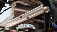
Here are some pics of my Guzzi Stelvio NTX Rostra cruise control installation. The main controller is mounted on a DIY bracket inside the right pannier mount. My wife made a nice waterproof sleeve that covers the unit and exposed wires and cables (no pic of that yet).
IMG 20150516 084229870

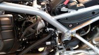
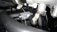
The cable wraps around to the left side and aligns with the throttle body linkage. A DIY bracket attaches the cable to the engine guard.
IMG 20150516 084330119 IMG 20150516 084229870 IMG 20150516 084330119
 
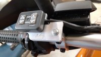
sorry about that double pic above. can't figure out how to delete. Anyway, here is the handlebar controls. Again, a DIY custom machined part. IMG 20150602 170951624
 
Back
Top