leafman60
Cruisin' Guzzisti
I serviced my 2012 Stelvio NTX swingarm today (15,000 miles) and captured a few images that may be helpful for anyone else doing this job. I recommend doing this chore in order to insure your bearings are properly lubricated and adjusted.
Sorry for the date stamps on the images.
Before launching into this procedure, I consulted anecdotal accounts, other postings as well as the factory shop manual that leaves much to be desired.
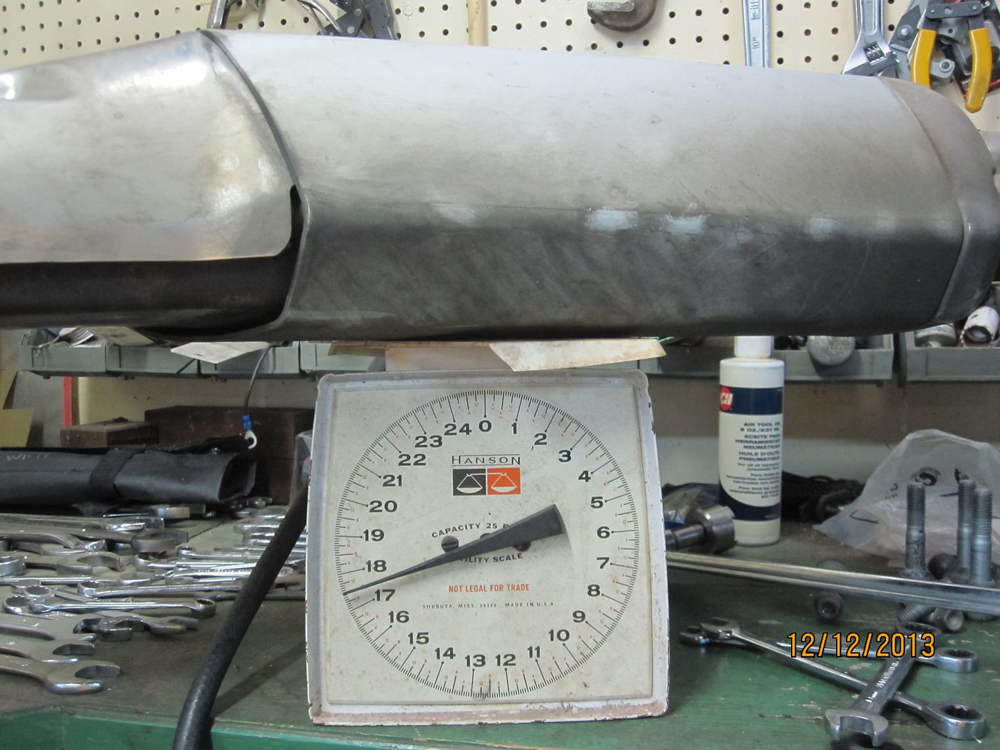
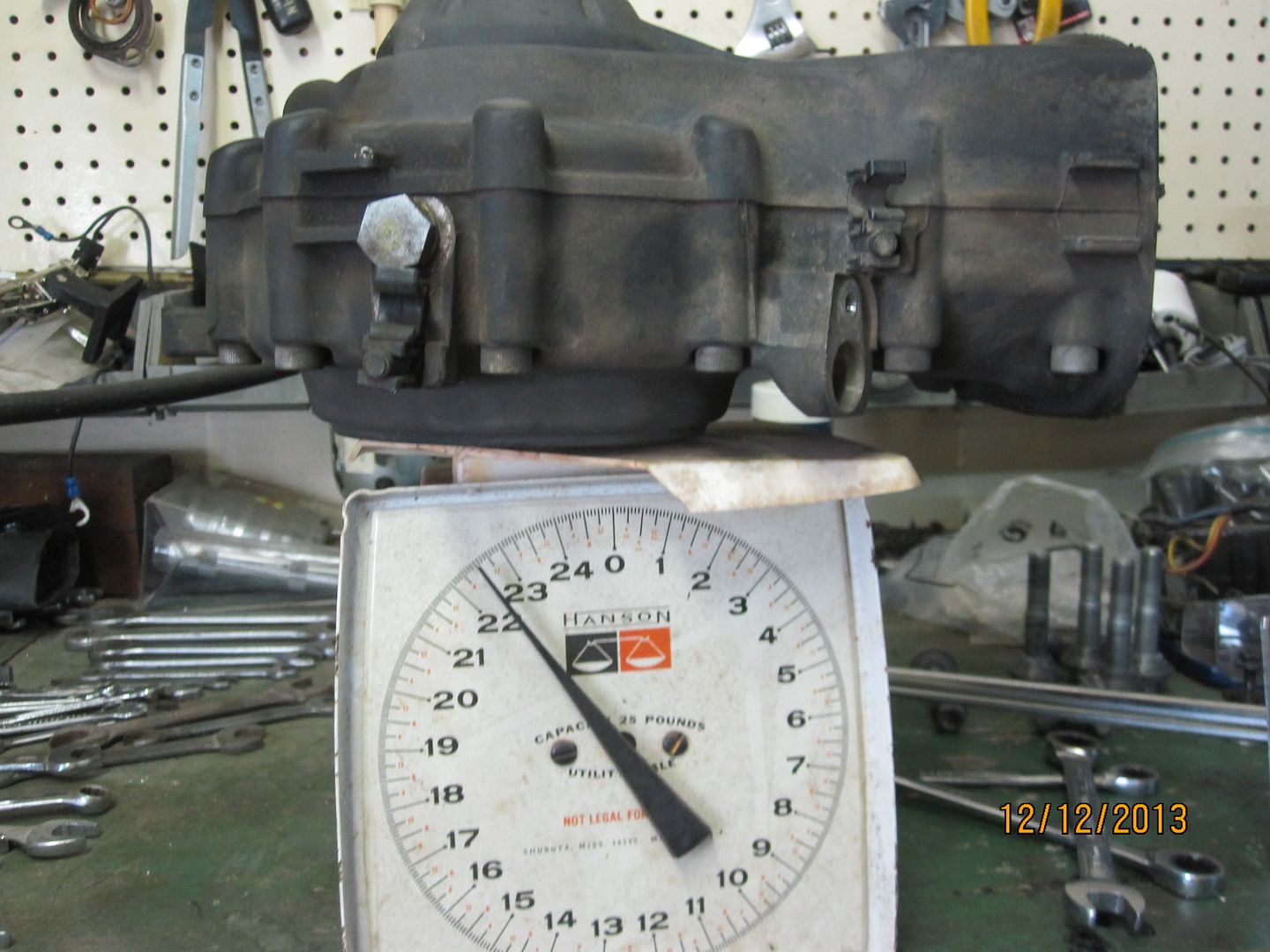
I first removed the muffler to provide better access. By the way, it weighs about 18 pounds.
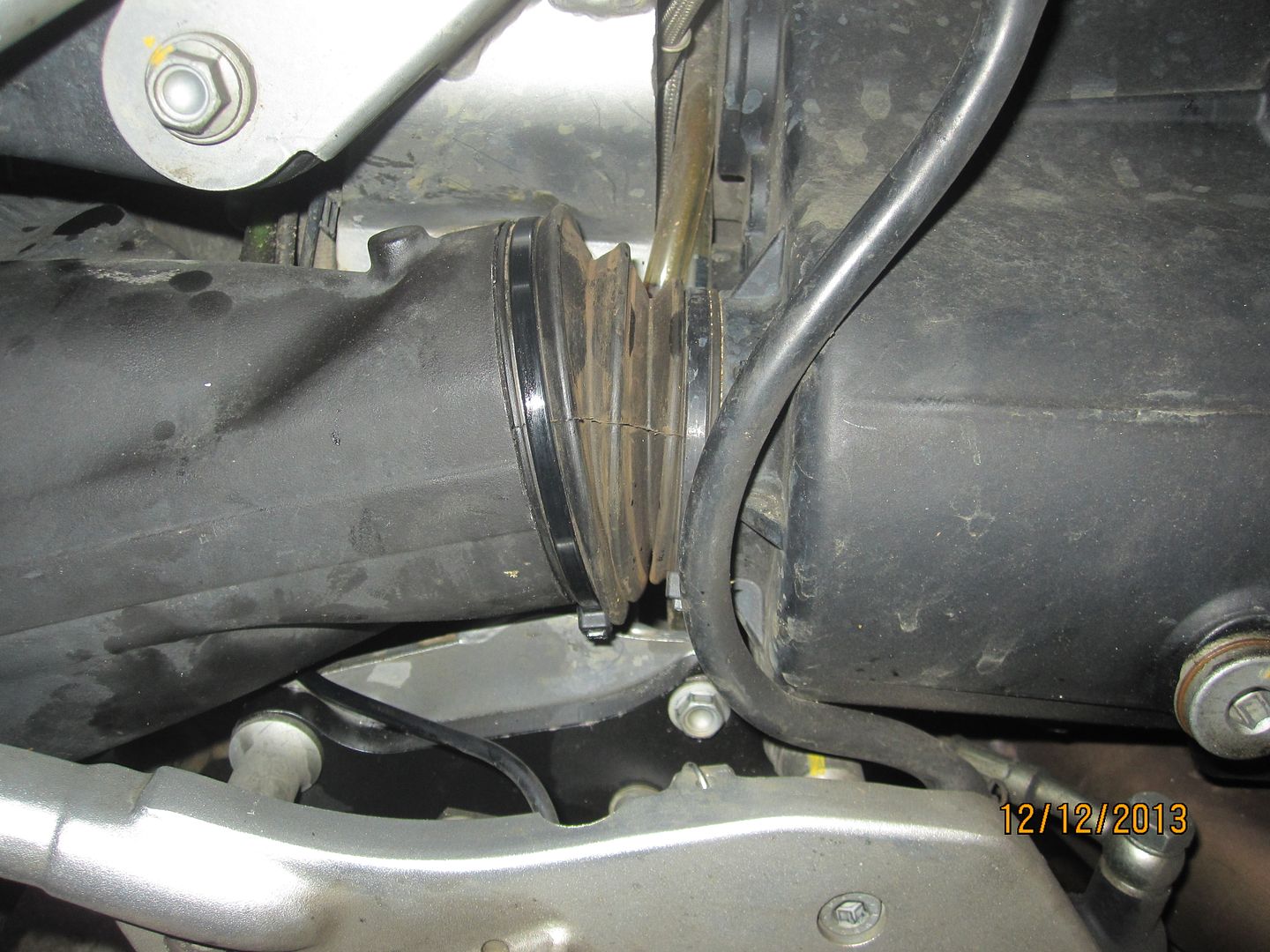
Next, the rear brake caliper was removed wrapped in protective plastic and set aside on the floor. The wheel was removed as was the ABS sensor, my tubing CARC, and all tubing was snapped out of the plastic retainers under the swingarm. Everything attached to the swingarm should be detached and laid aside. The control arm was then unbolted and tied up out of the way. Cut the big diameter nylon tie off the boot where the swingarm attaches to the transmission and pull the boot away from the swingarm.
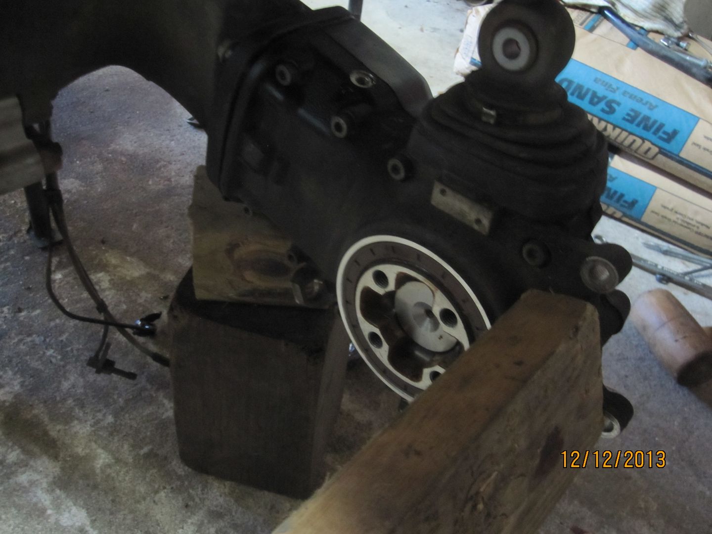
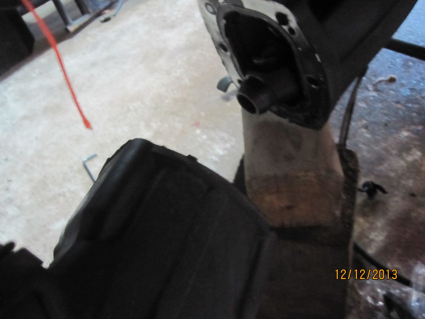
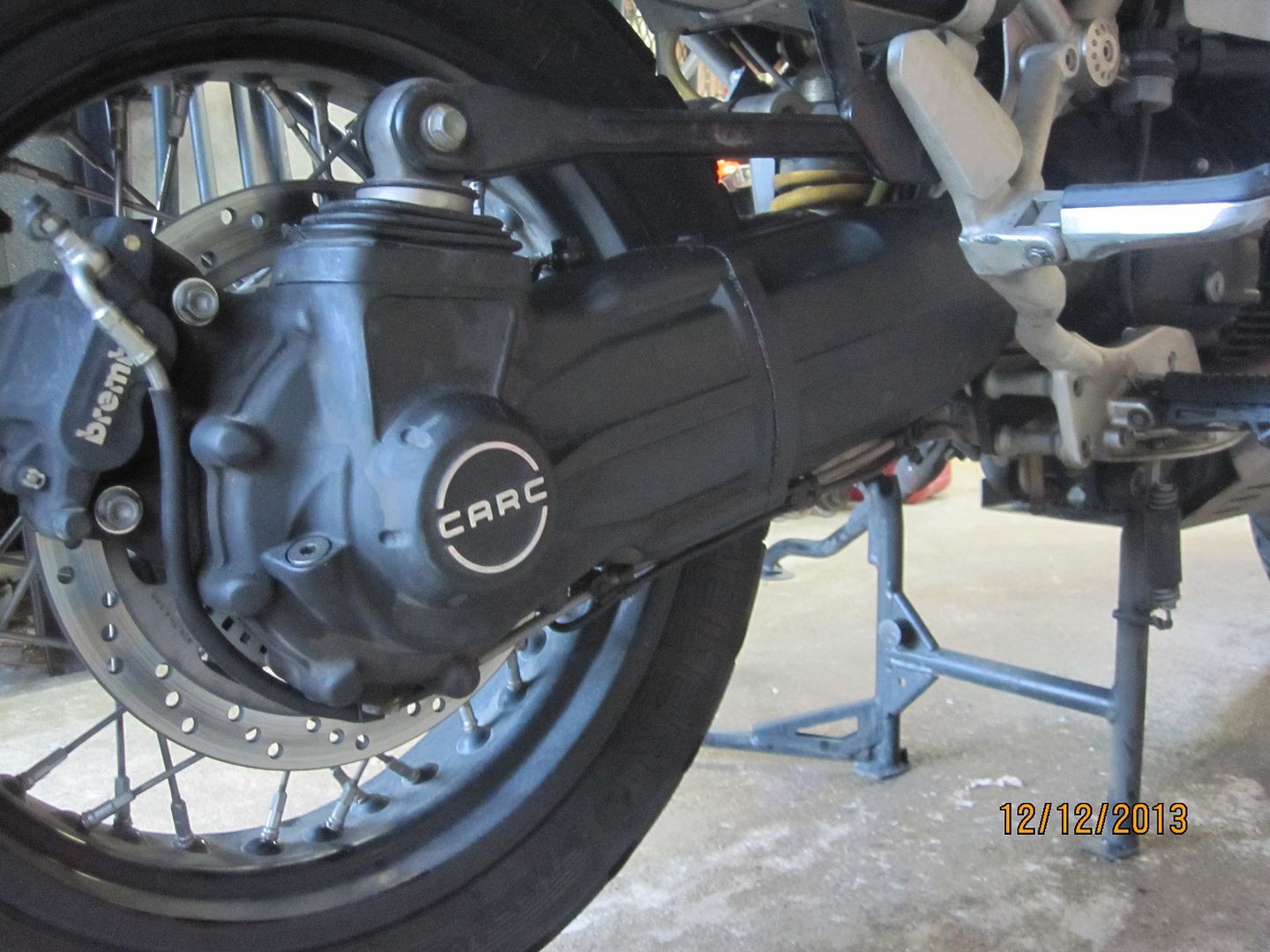
I placed a wooden block under the CARC for temporary support.
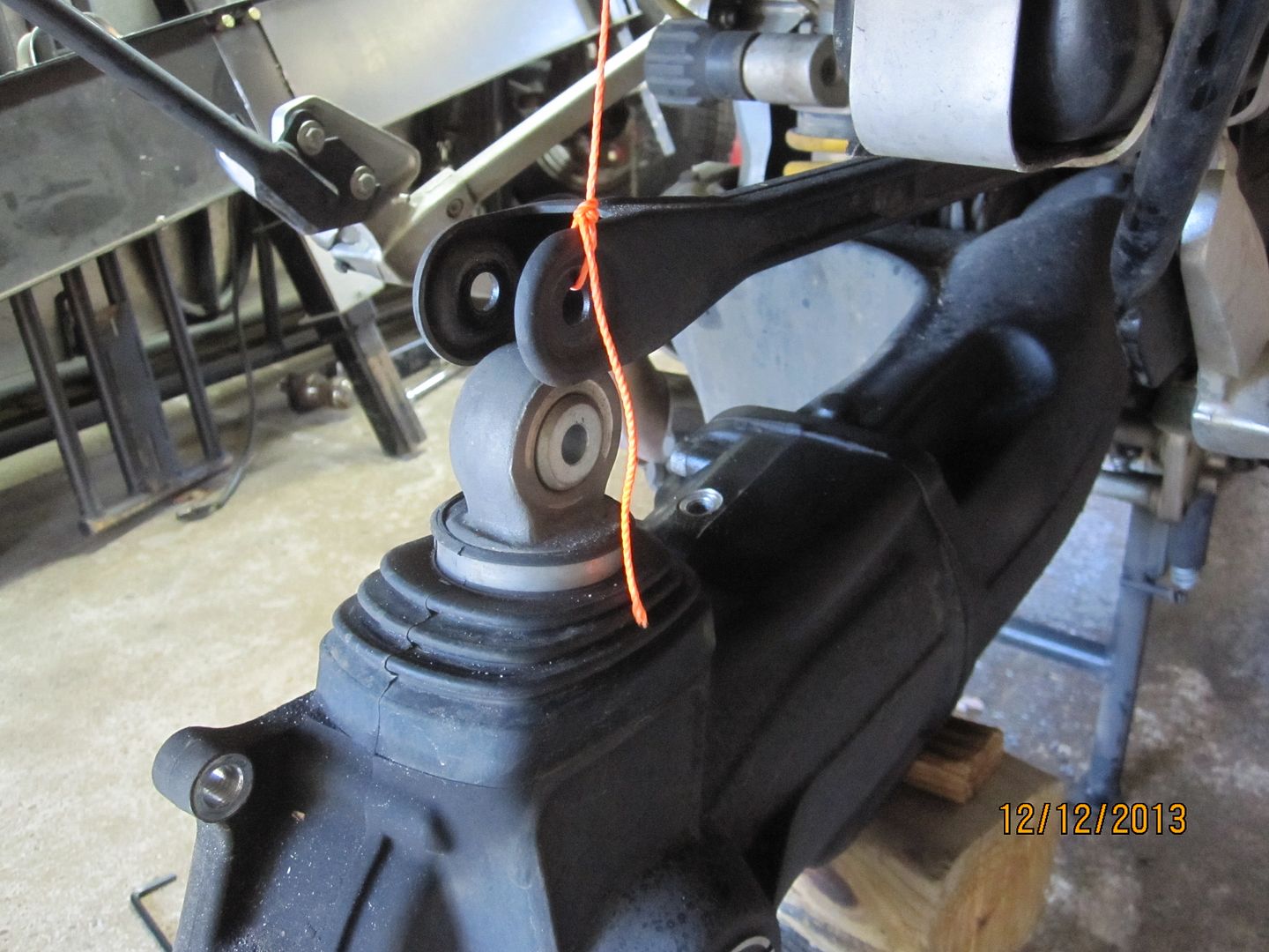
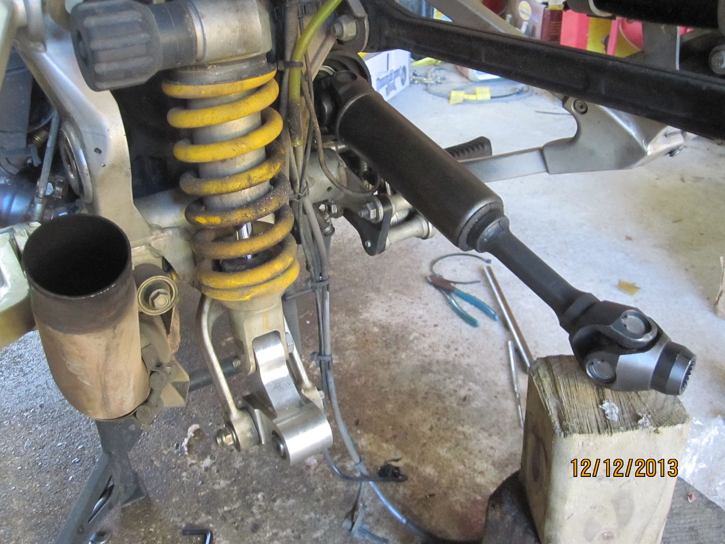
The shock absorber link connection to the swingarm was then unbolted.
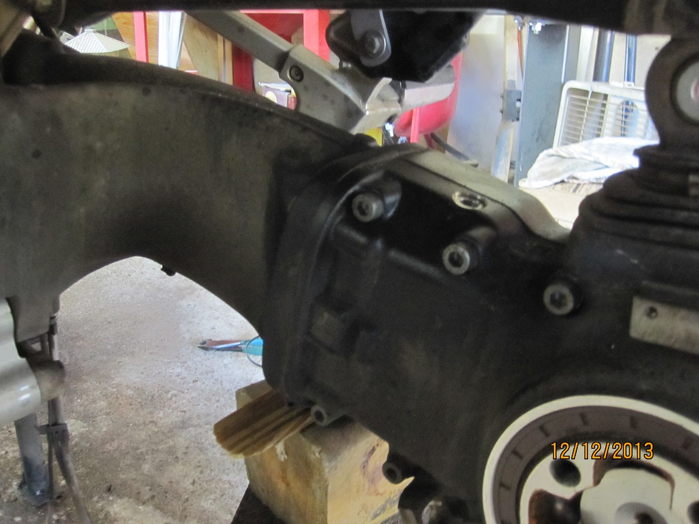
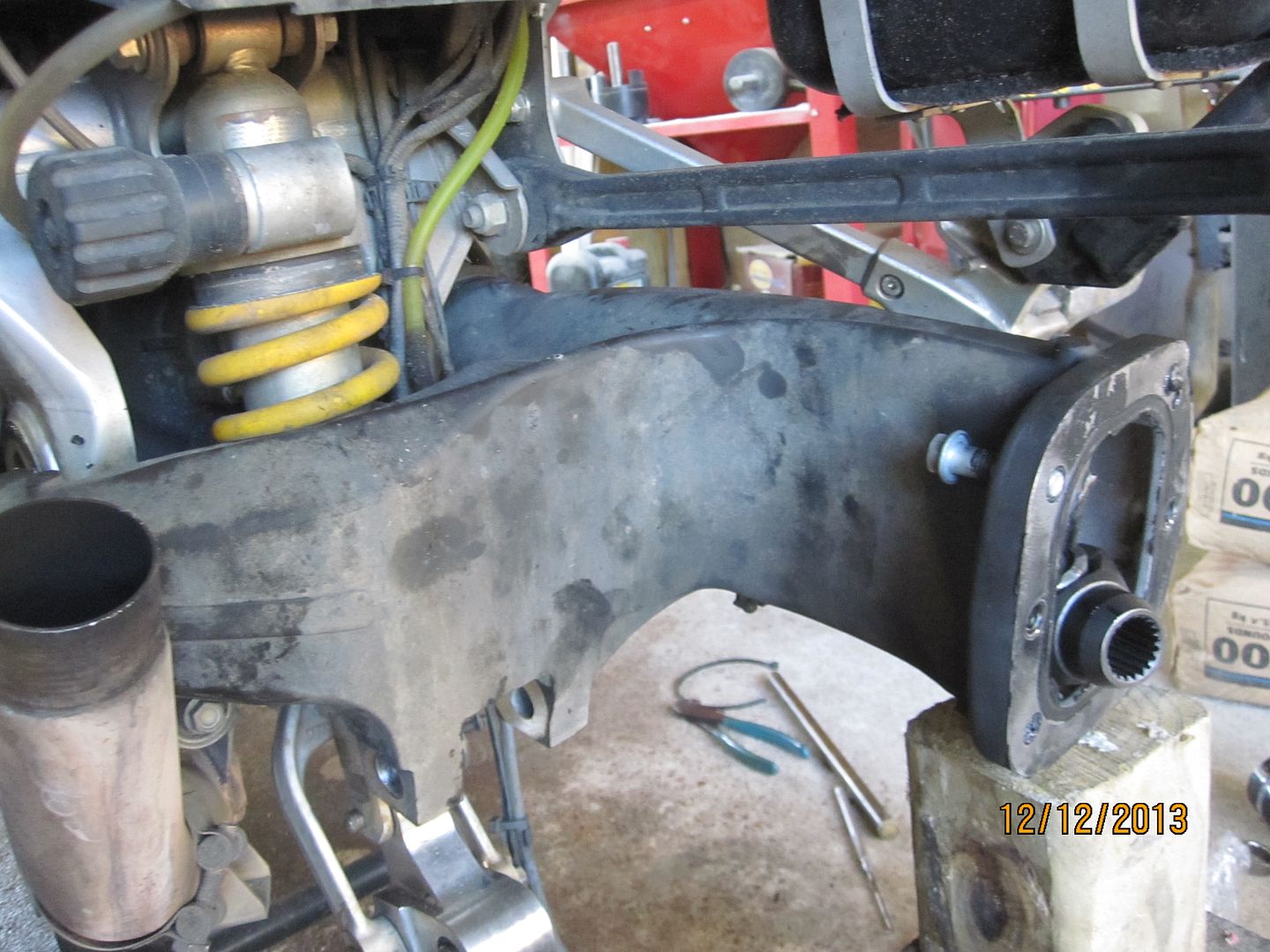
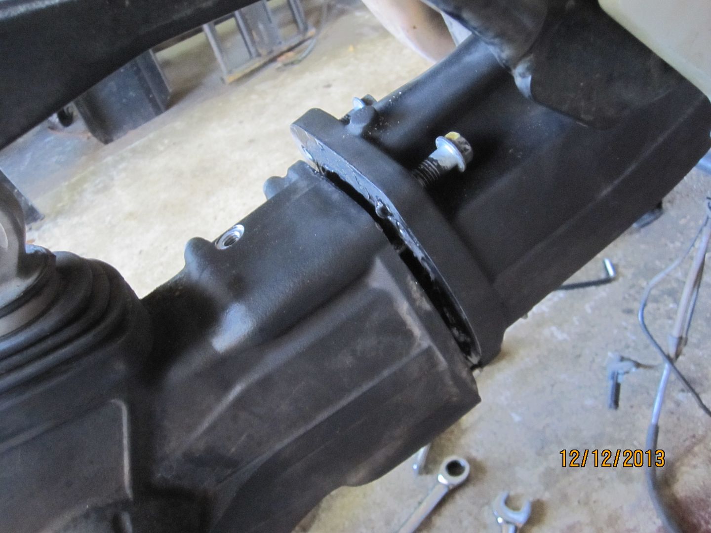
Next the final drive or CARC had its four bolts loosened but not totally removed. A piece of wood and a mallet was then used to gently rap the CARC loose from the sealer that had been used when it was previous bolted to the swingarm.
The 4 CARC bolts were then completely removed, the CARC easily pulled off and set aside. Though position of the driveshaft vis-à-vis the CARC is not critical, I marked my shaft ends since I wanted to later reconnect the shaft on the splines in the same position from where it came.
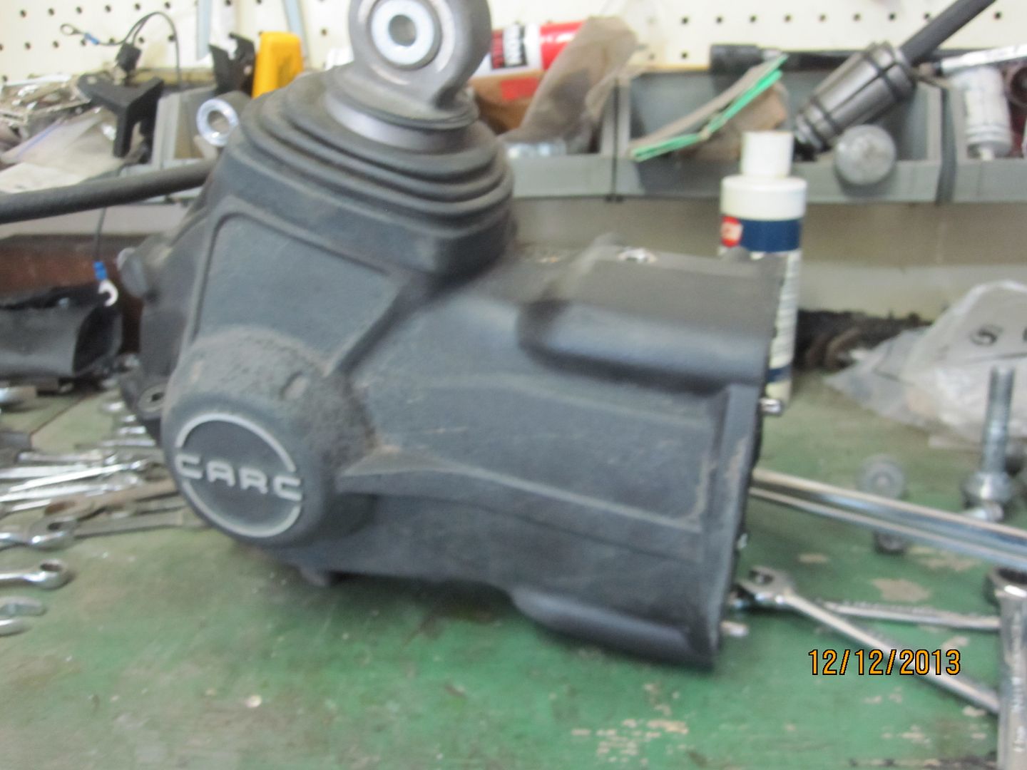
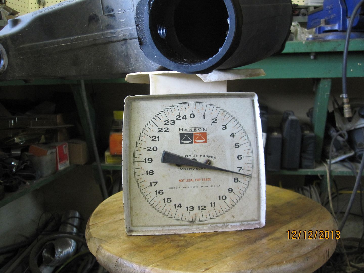
By the way, the CARC weighs 22.5 pounds.
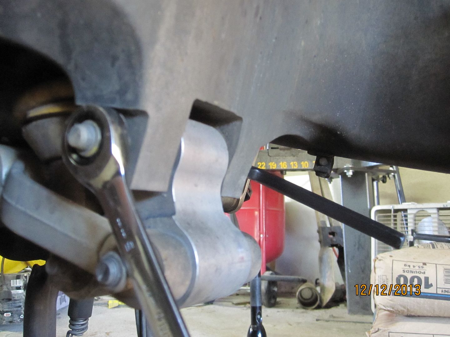
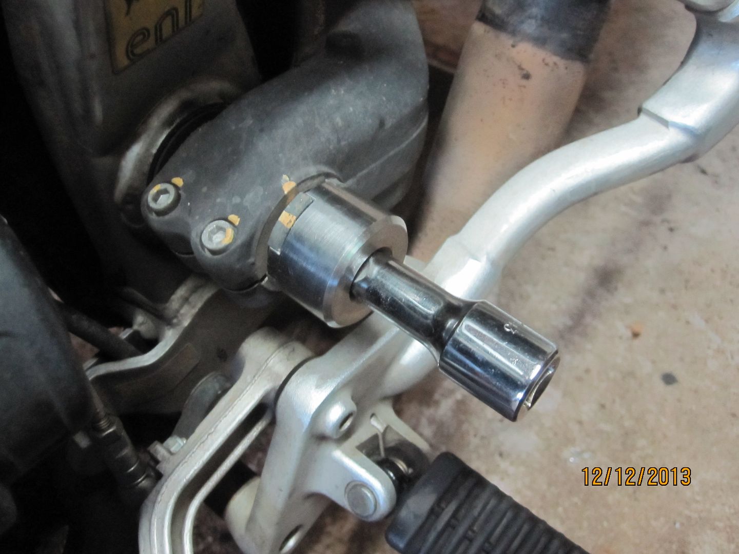
Next, the two pinch bolts on the left side of the swingarm were loosened.
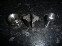
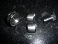
Then the special castle nut tool was used to remove the preload bushing. This bushing is tightened only to 10NM so it is easy to remove.
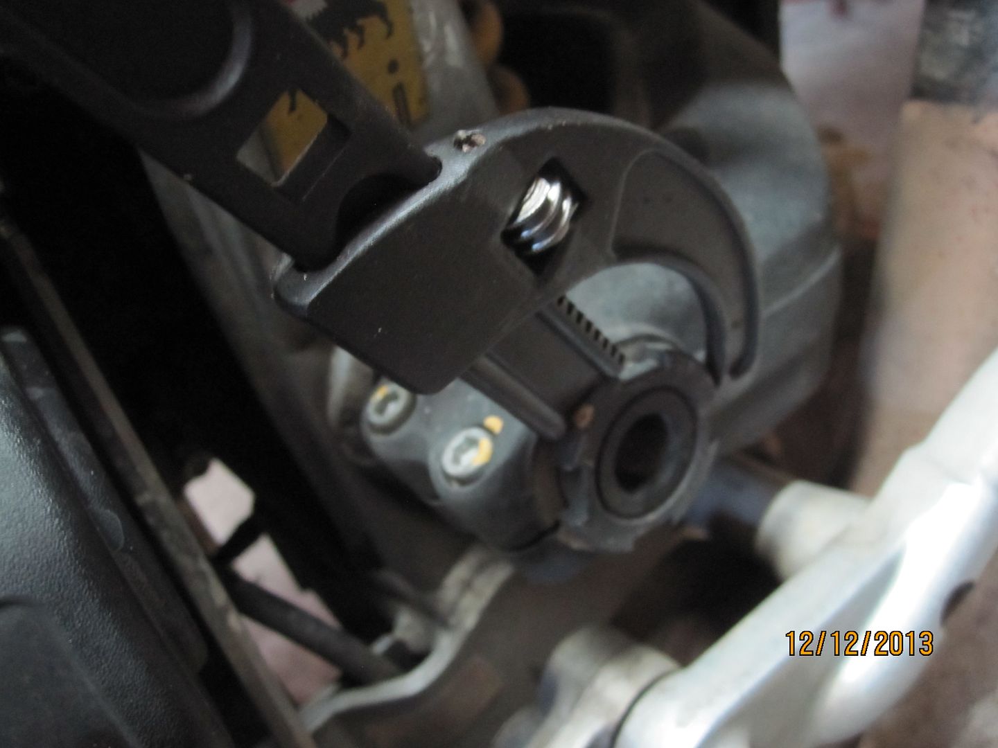
If you do not have the special castle nut tool, any adjustable hook wrench would work for removal.
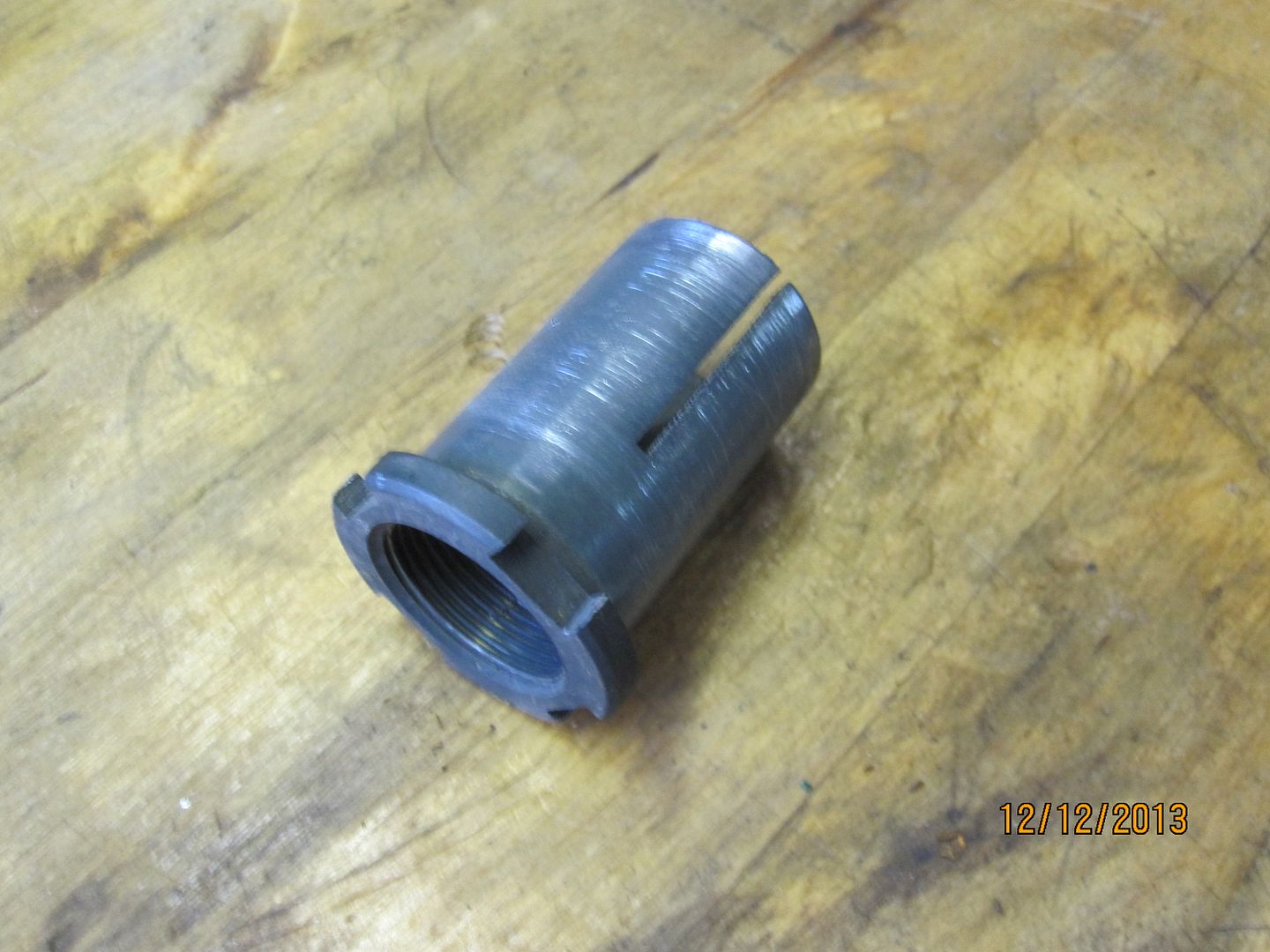
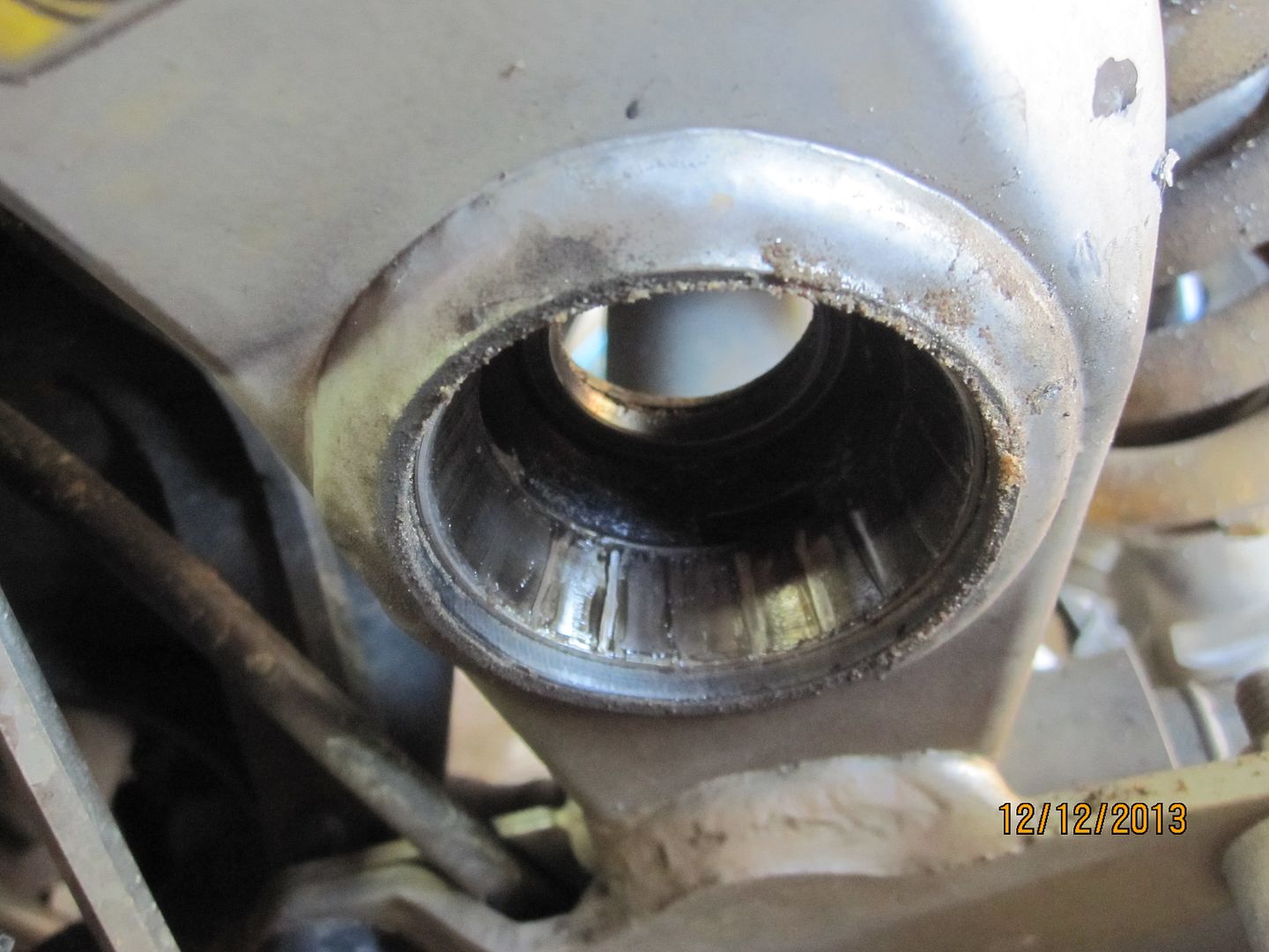
The preload bushing is removed from the swingarm pivot pin and set aside. More on this part later.
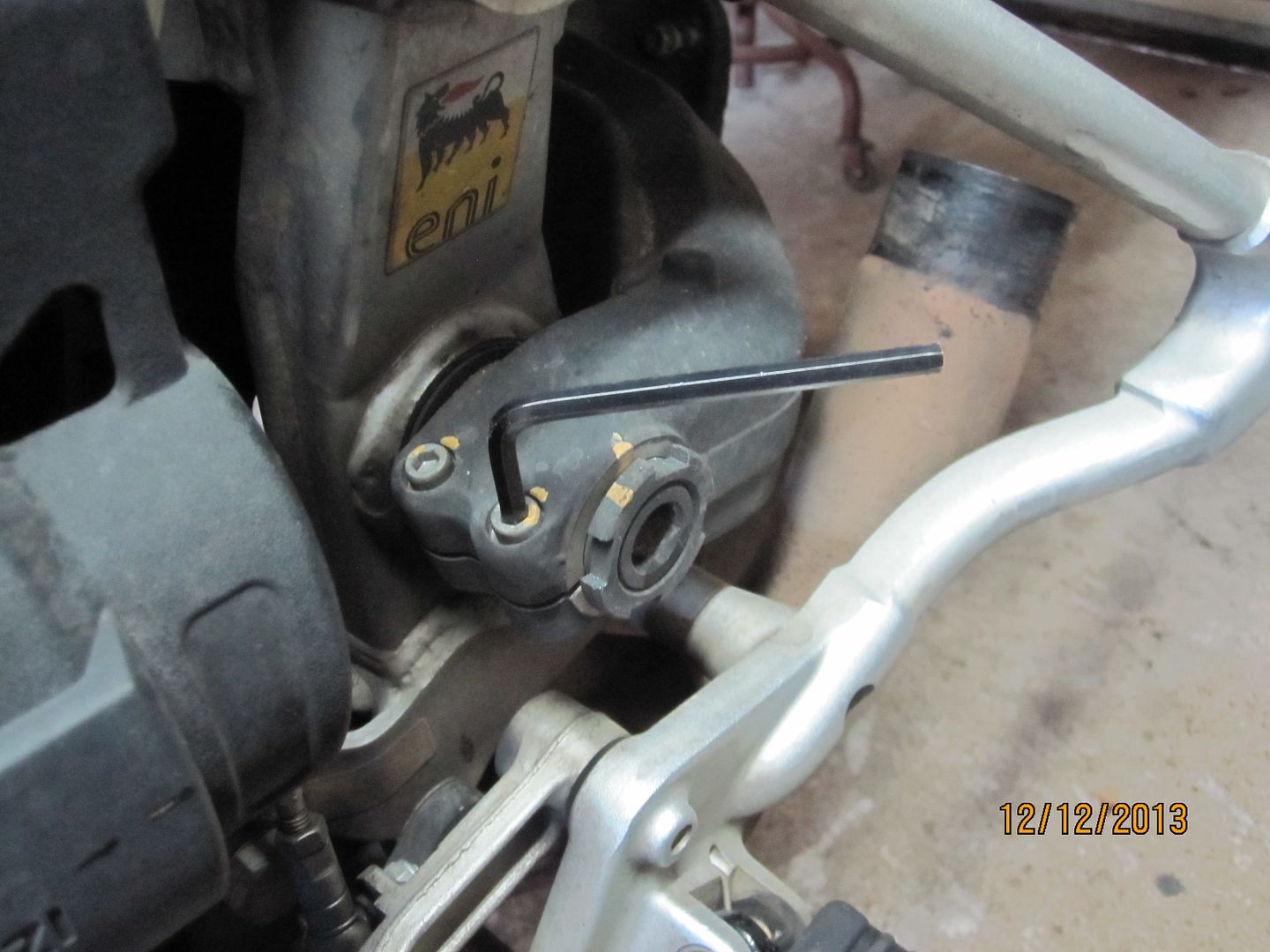
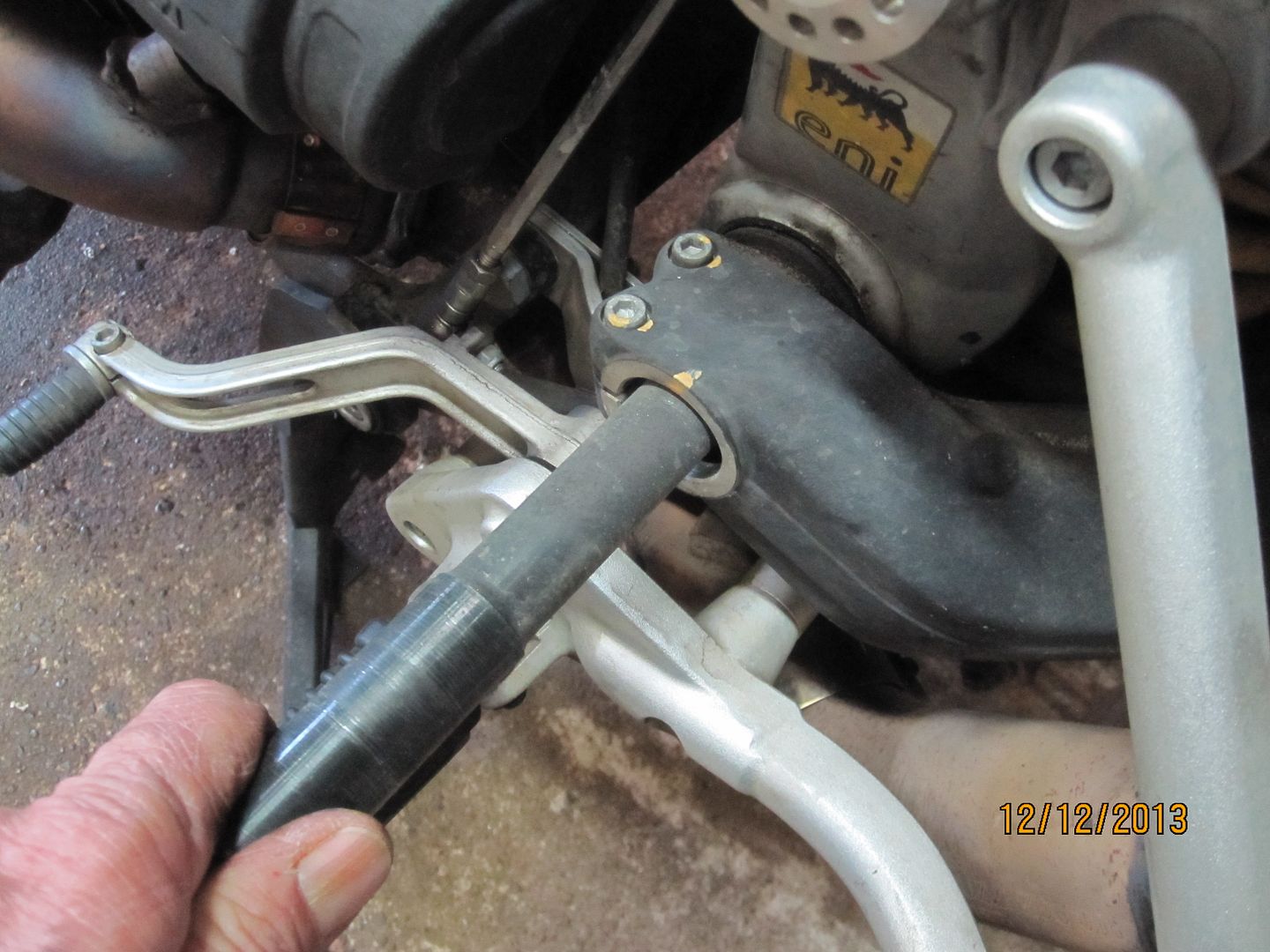
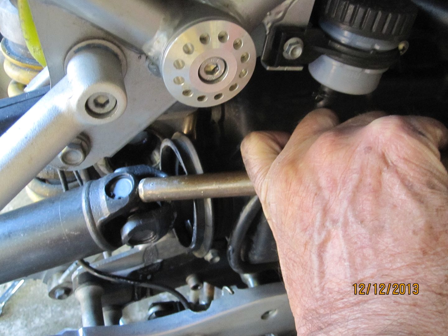
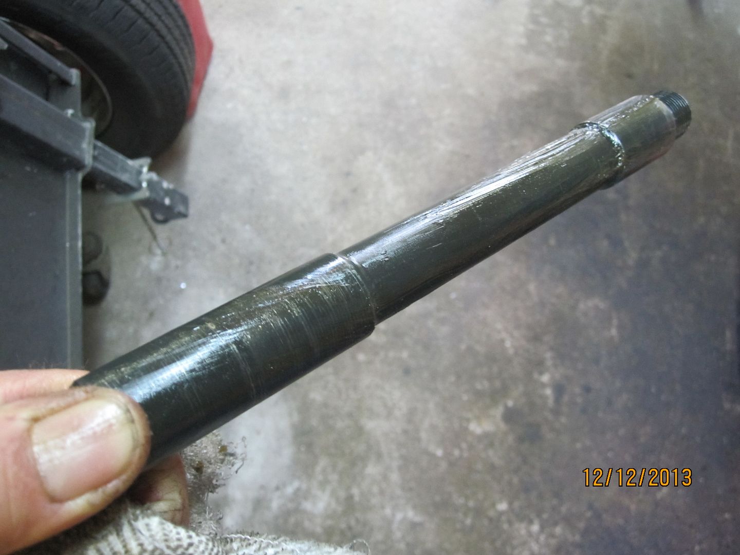
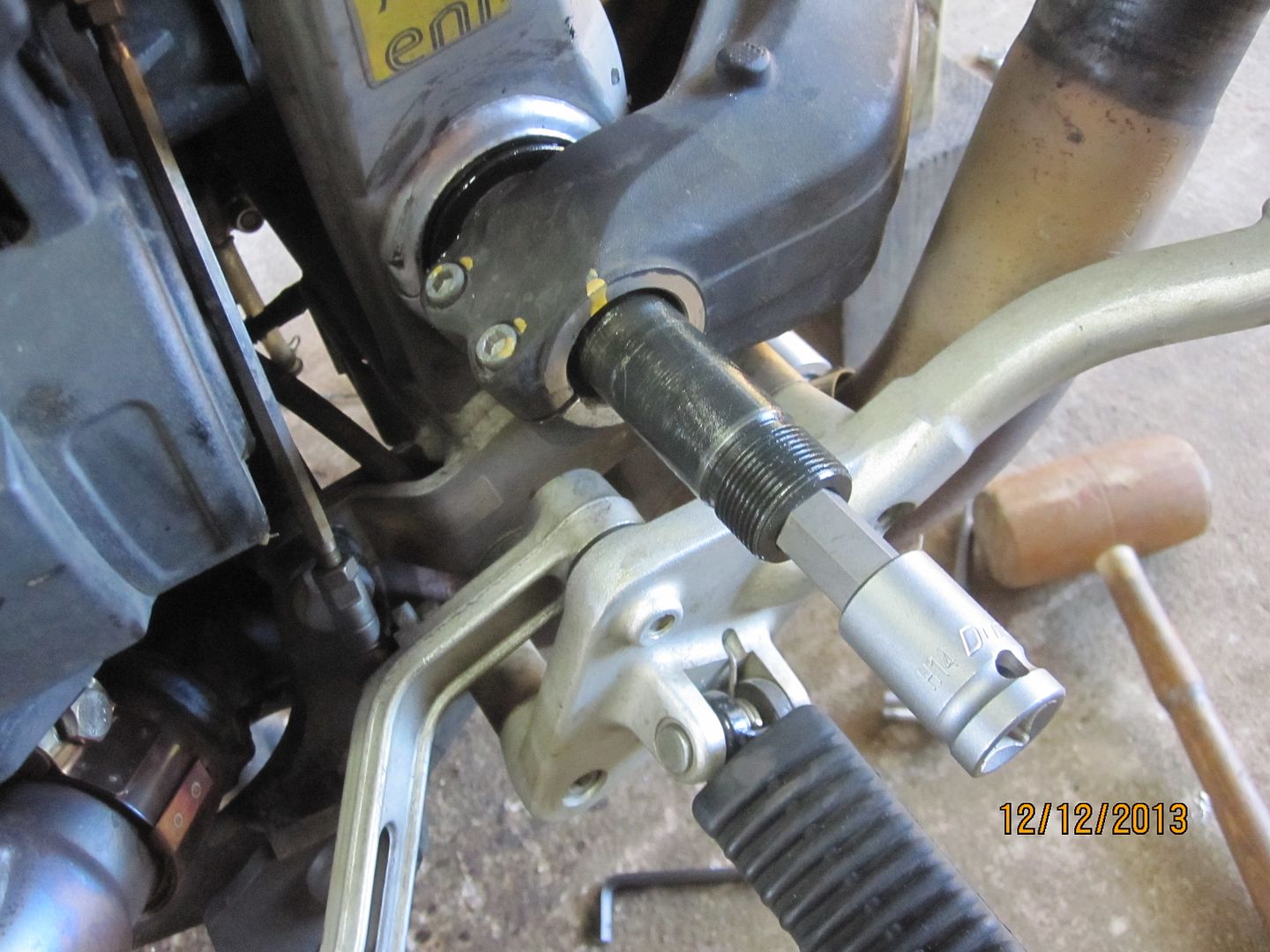
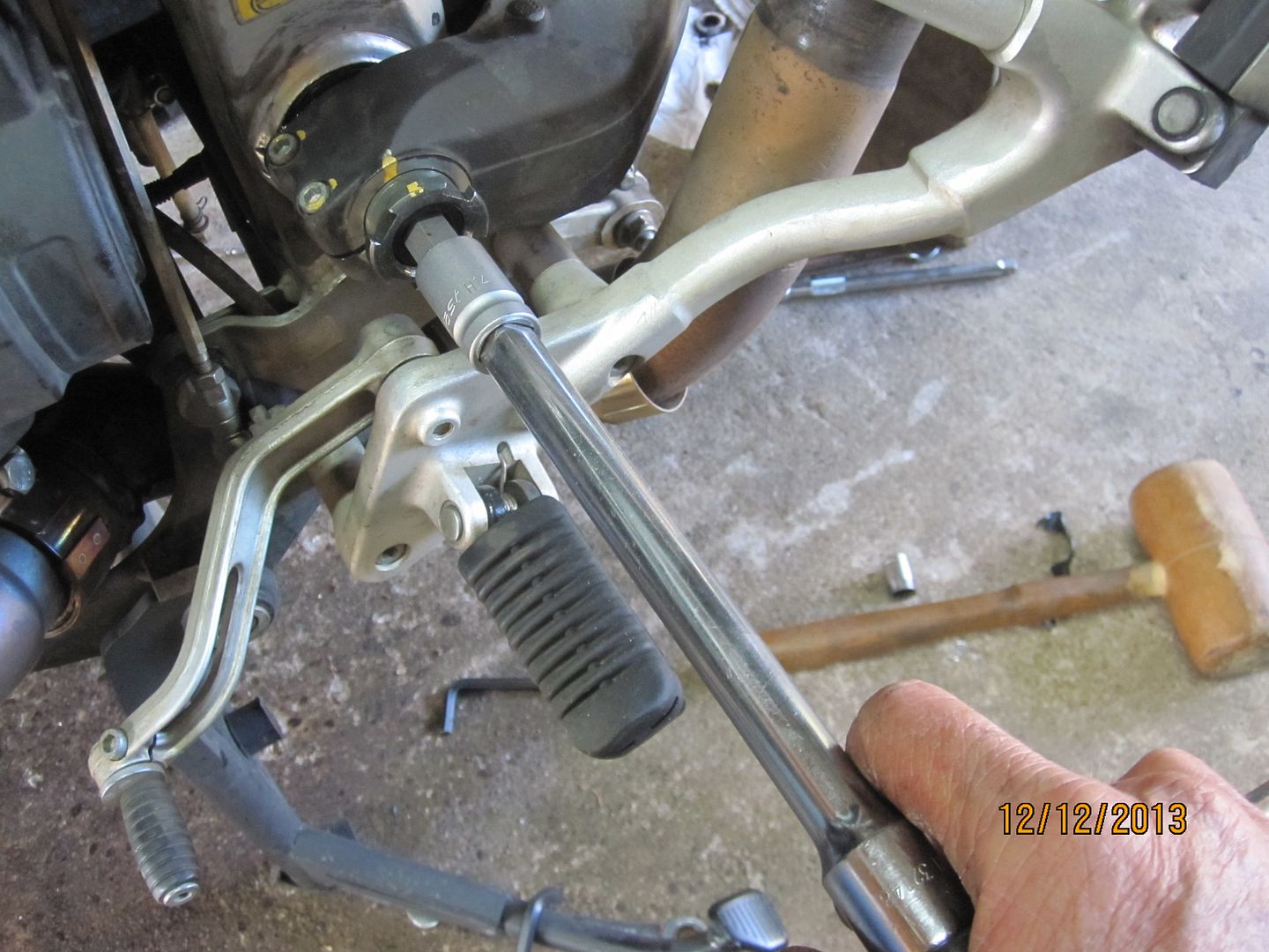
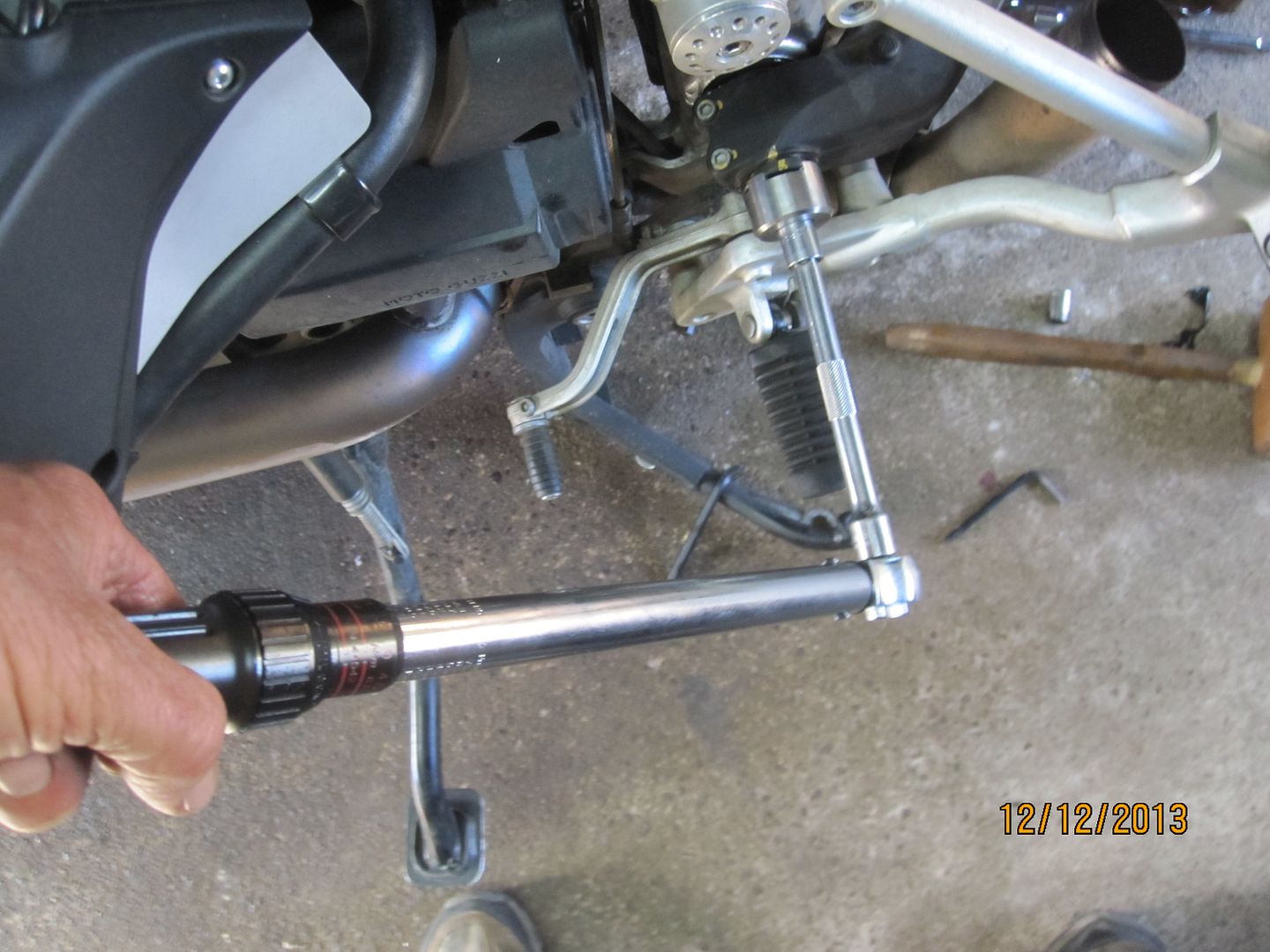
Next, the swingarm pivot pin is removed with a large hex or Allen tool. My pin was not even finger tight and it should have 60 NM of torque.
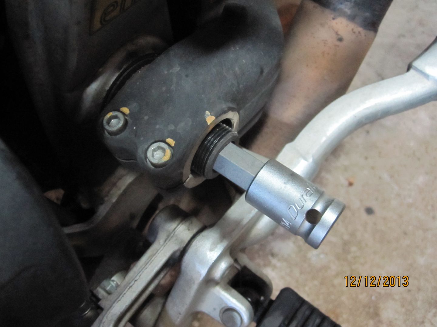
The swingarm pivot pin is removed while steadying the swingarm with another hand.
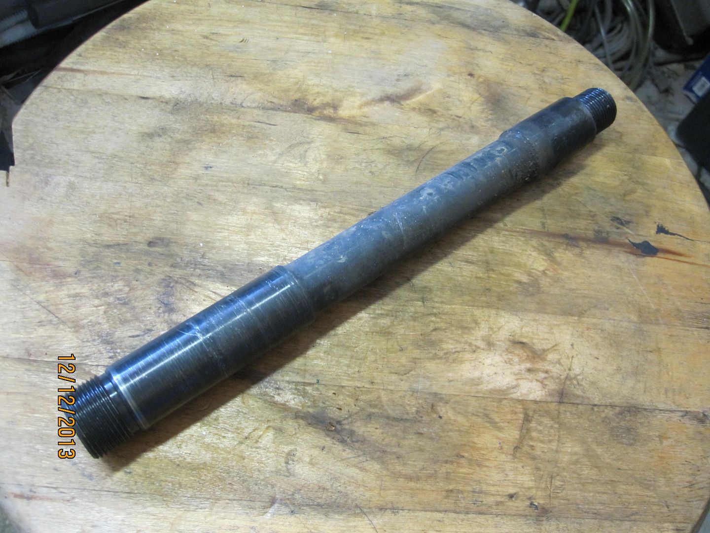
The swingarm pivot pin.
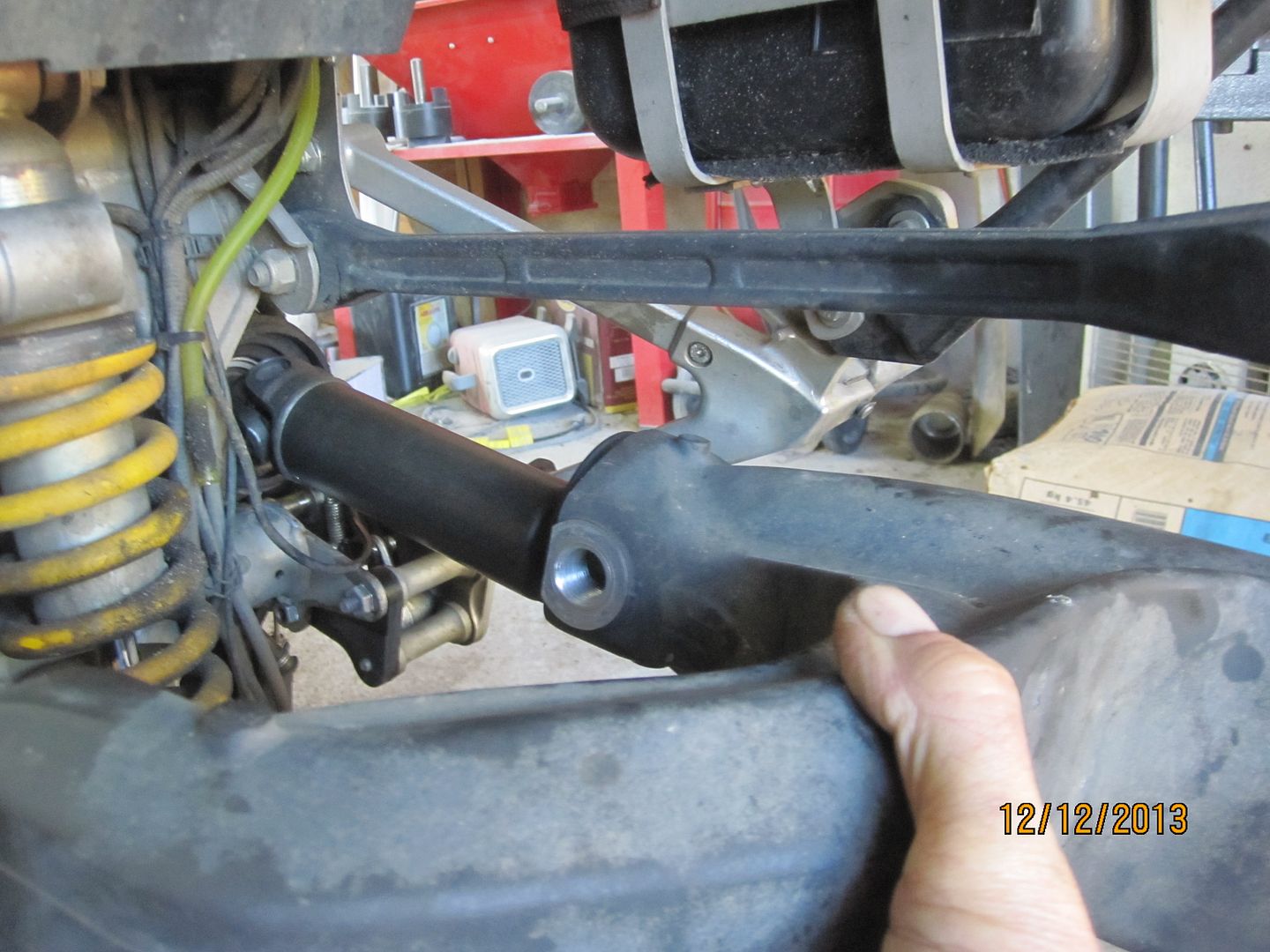
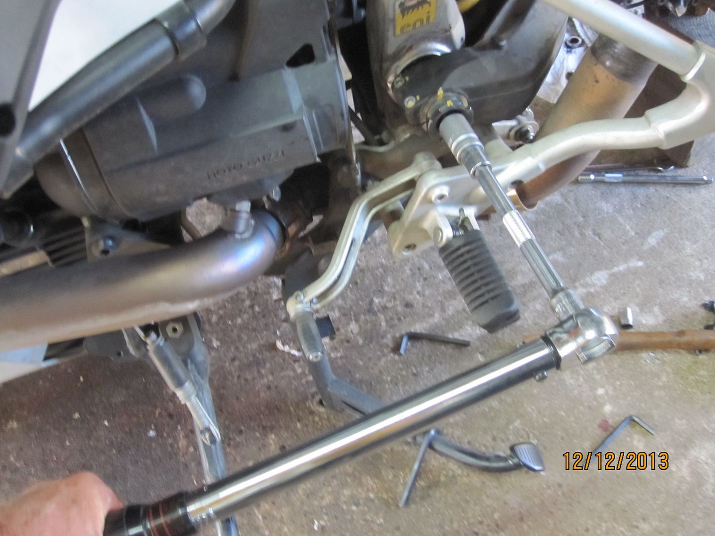
Next, leave the driveshaft attached and just easily work the swingarm out and off the driveshaft and set the swingarm aside.
Be careful not to lose this insert in the left side bore of the shock linkage bolt bore.
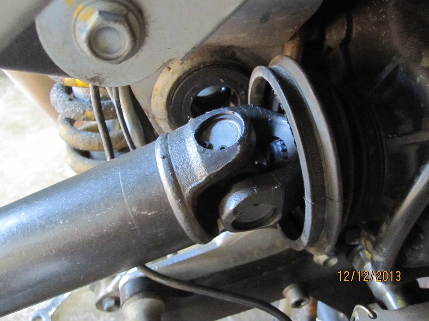
You do not have to actually remove the driveshaft to service the swingarm bearings. However, I wanted to wipe the splines of its connecting shaft with grease (none was there) so I removed the shaft. Using a drift on the U joint, a smart rap will release the shaft from the splines where it is retained by an internal spring clip. This procedure does not damage the the retaining clip so don't worry.
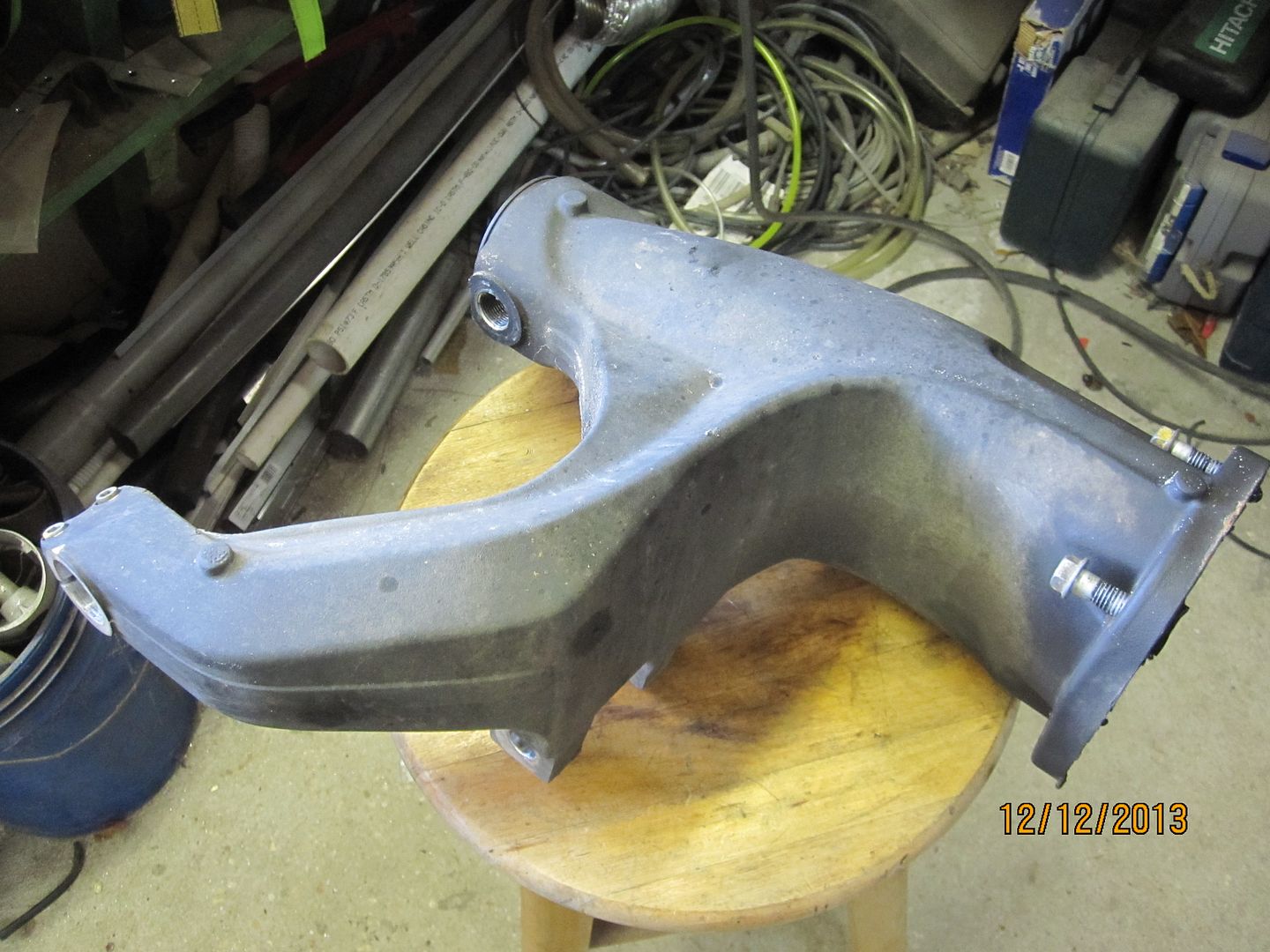
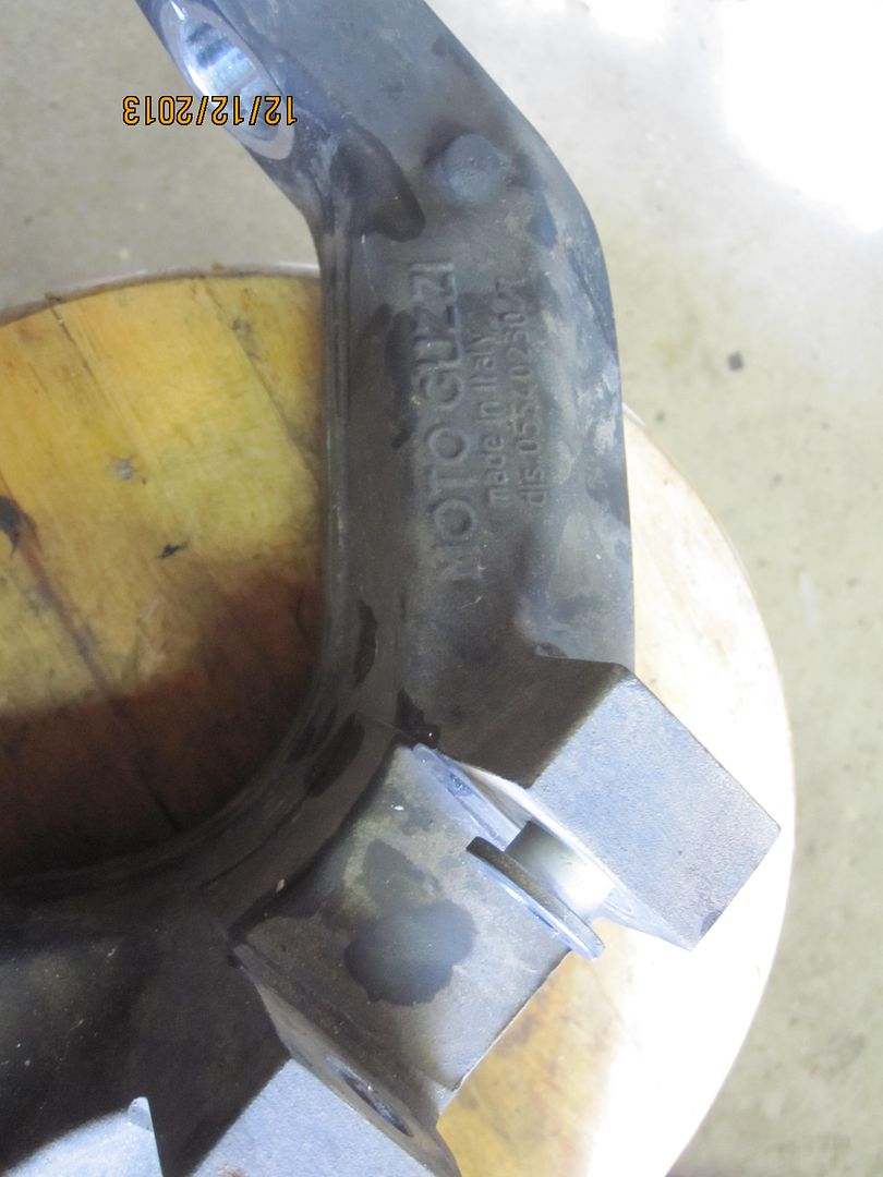
The swingarm itself weighs 7.5 pounds.
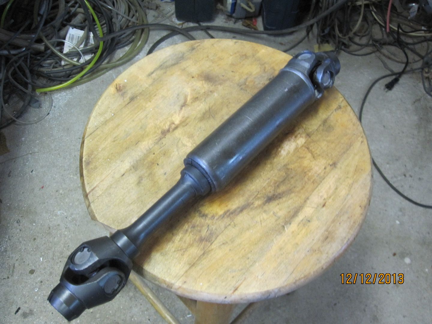
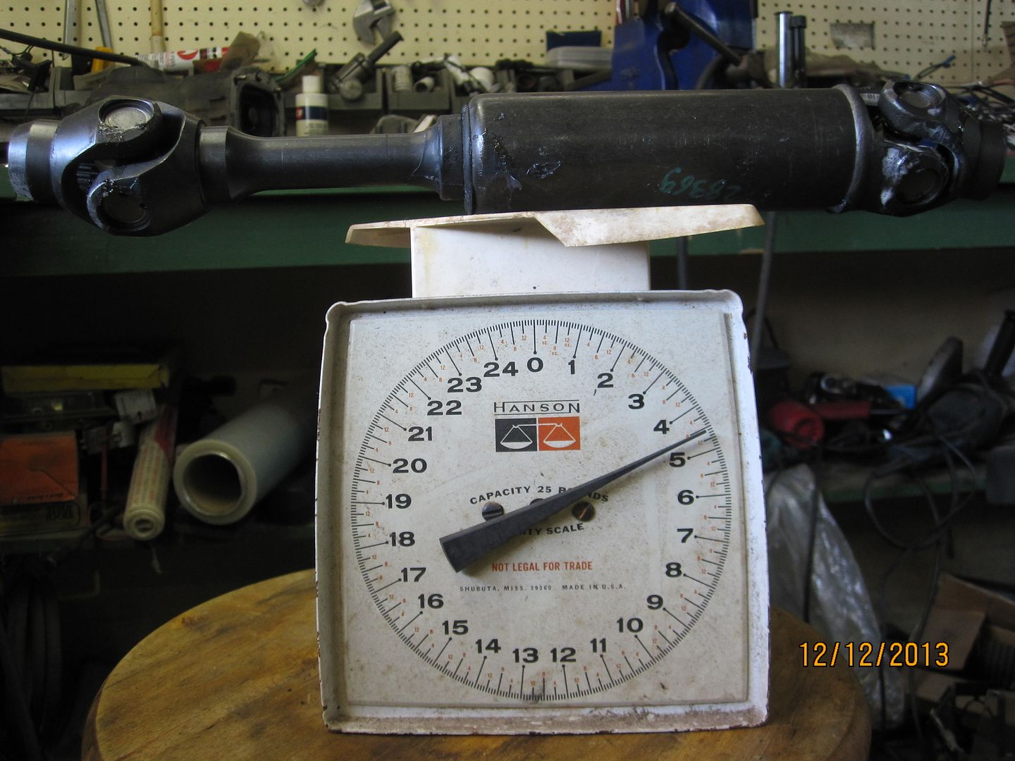
The driveshaft weighs 4.5 pounds. The total weight of the swingarm, shaft and CARC is 34.5 pounds.
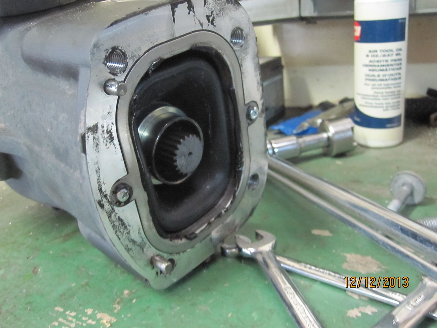
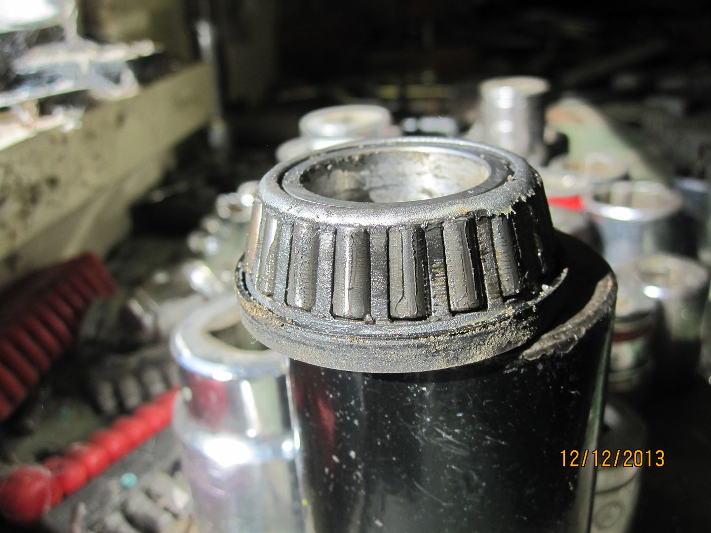
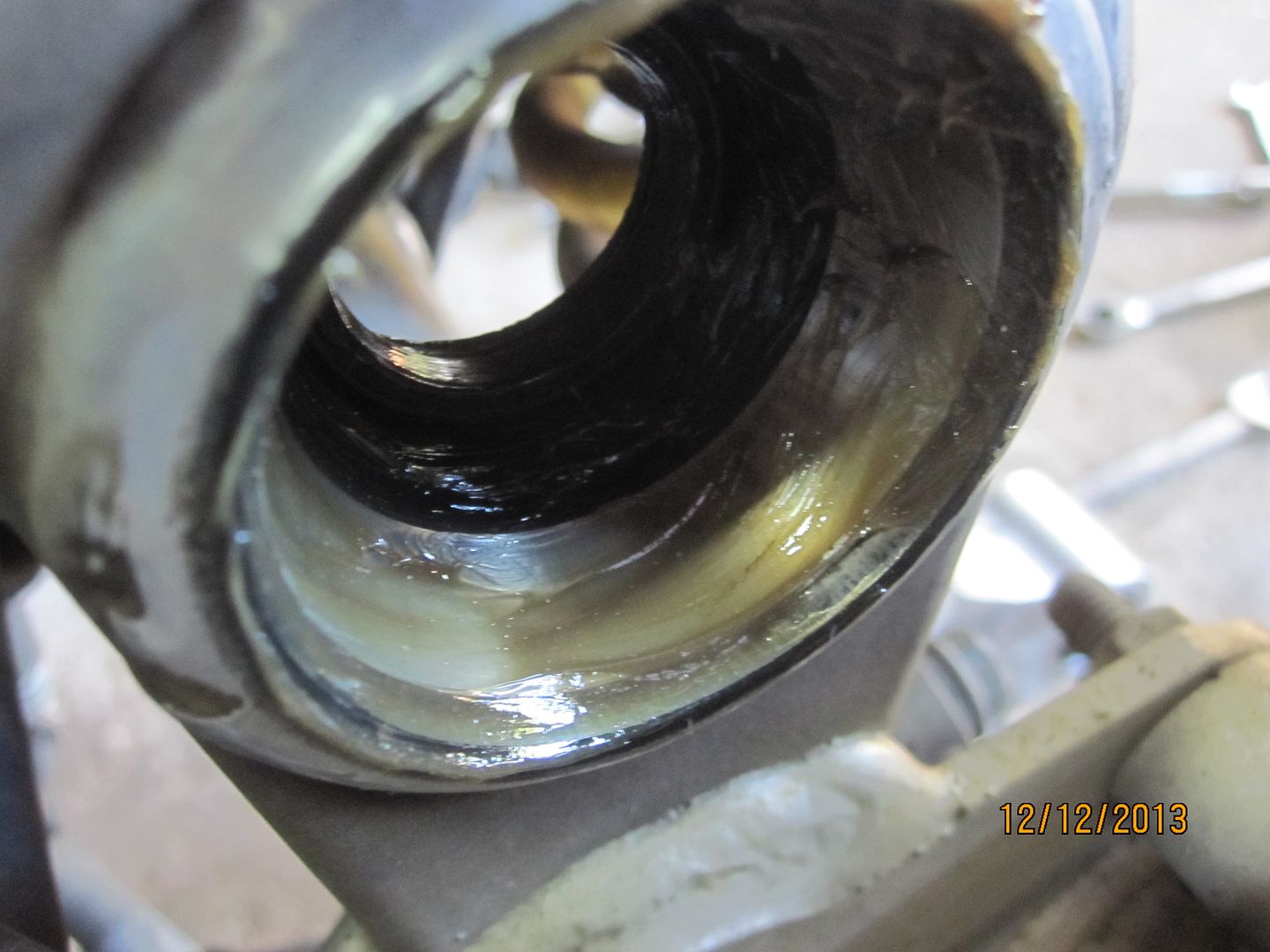
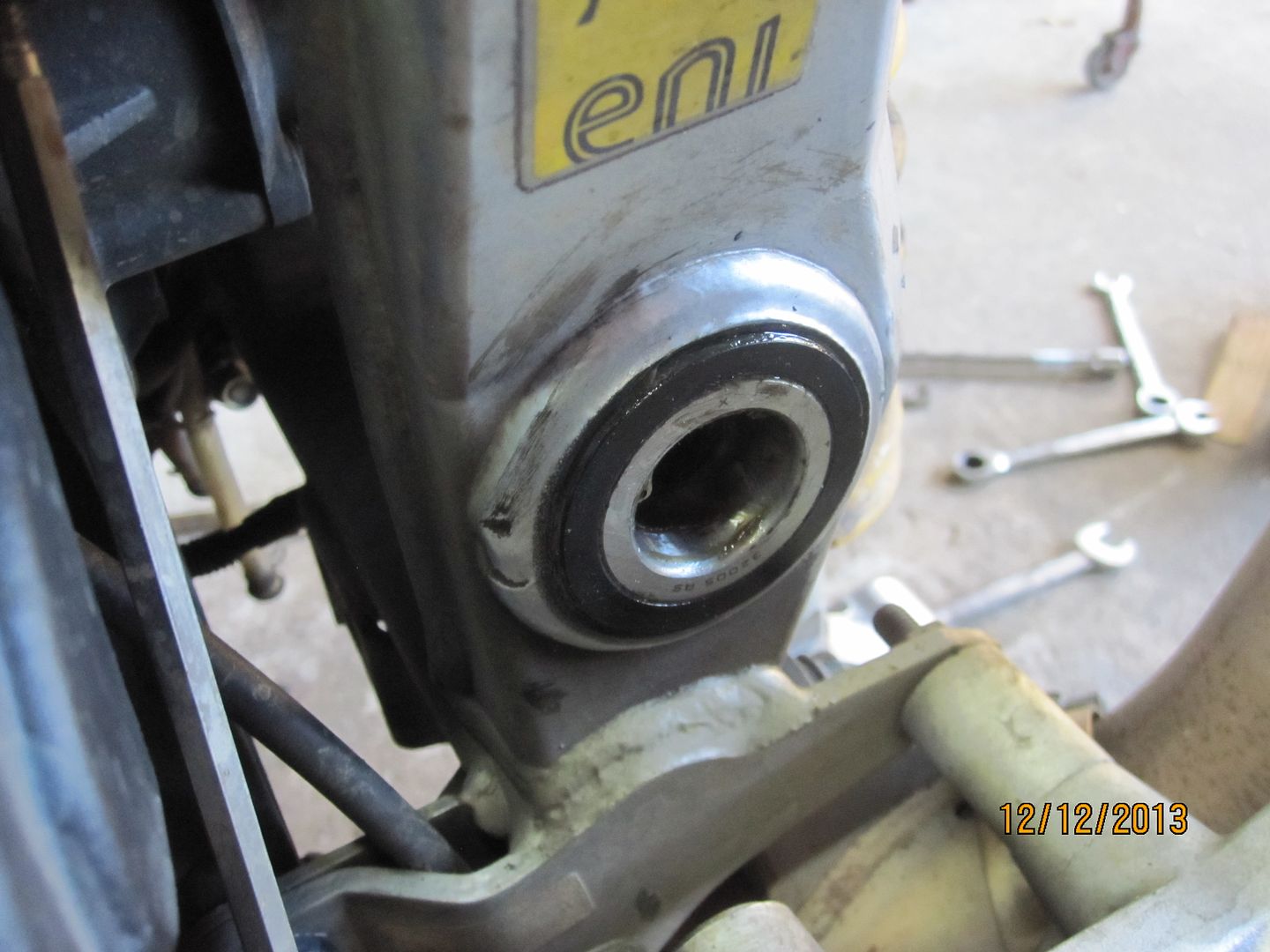
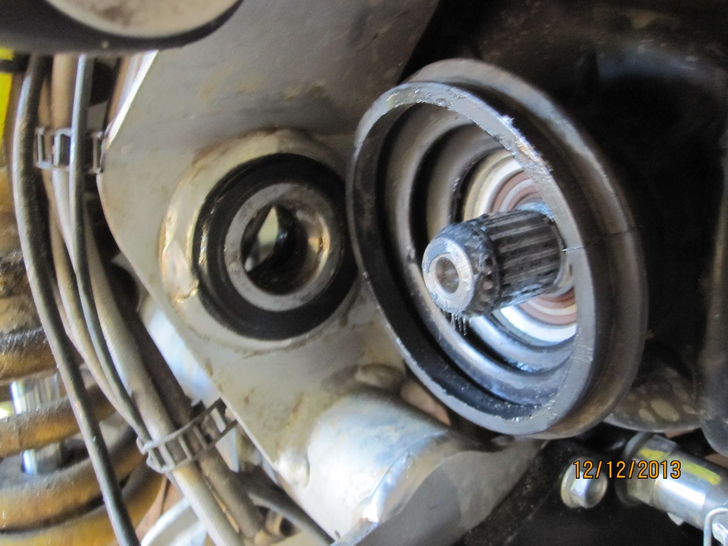
You can see the bearing and its rubber seal here on the right side of the machine. The seals just pull out of a shallow bore and the bearings just fall out of their races.
My bearings had minimal grease. Thankfully, they cleaned up nicely and did not show permanent scars or marks.
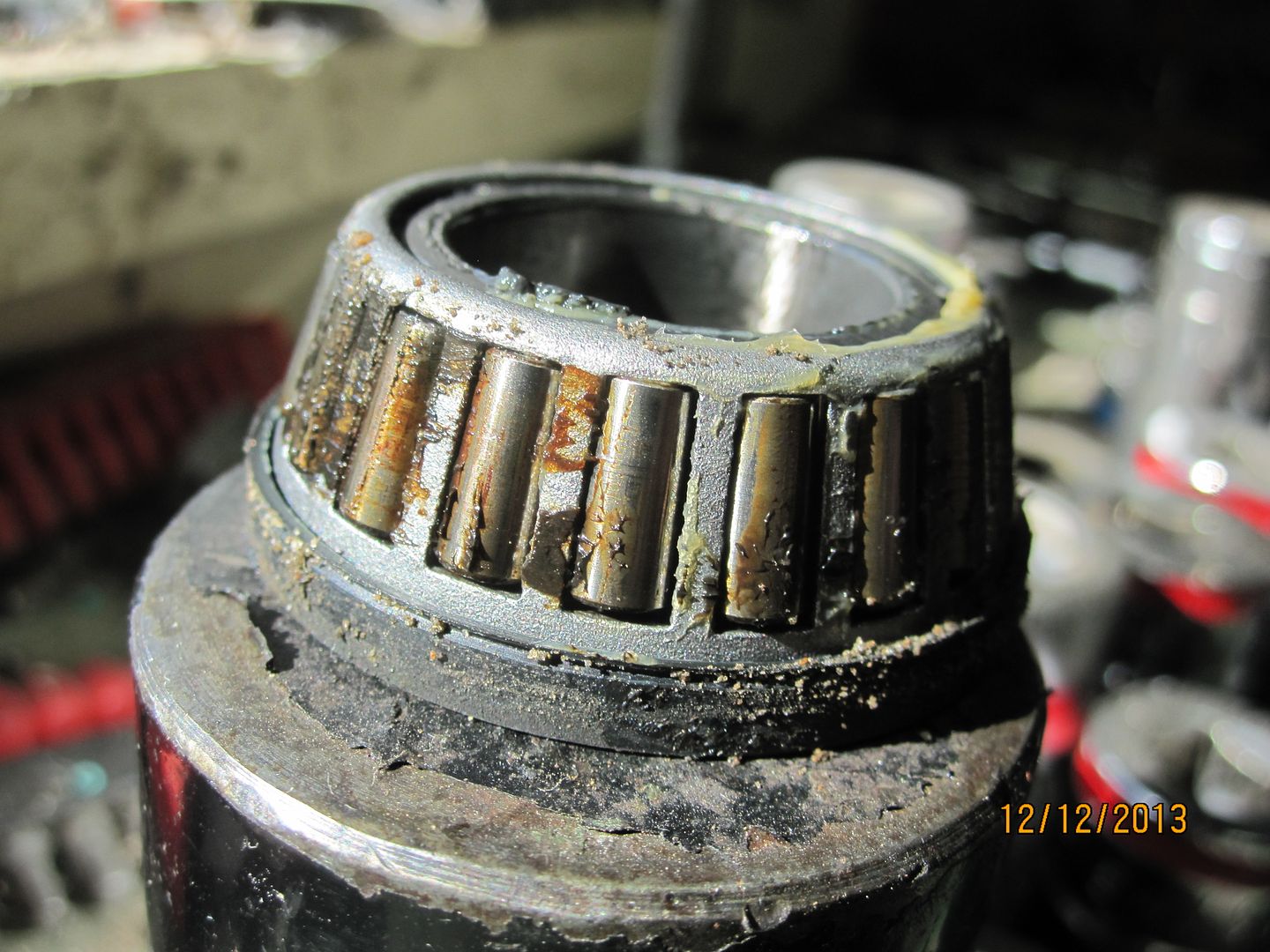
Everything was cleaned-up. The bearings were packed with Teflon additive grease, the races wiped with the same and the bearings with seals positioned back into their bores. The seals were just fine but, in retrospect, I'd use new seals anyway.
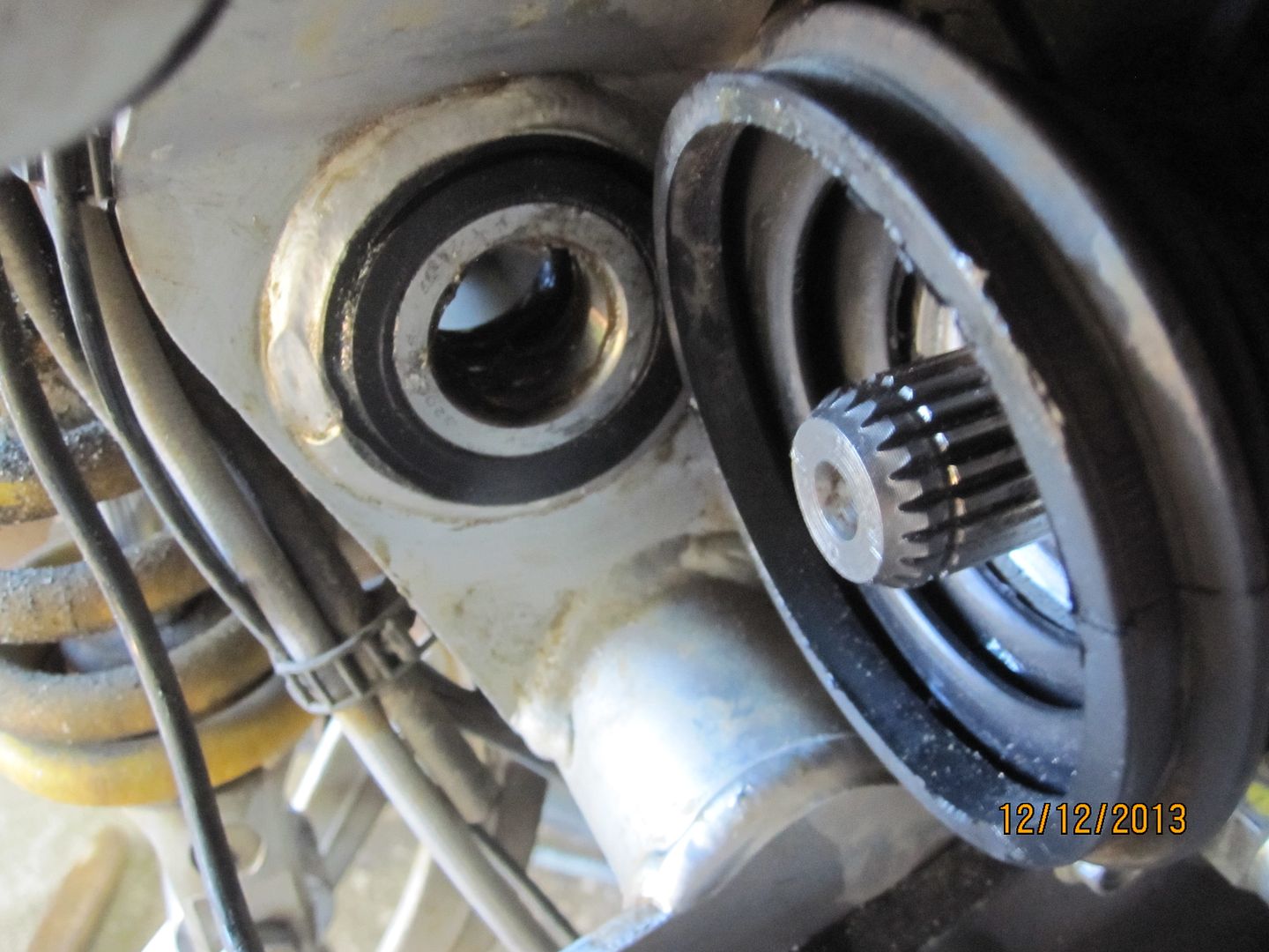
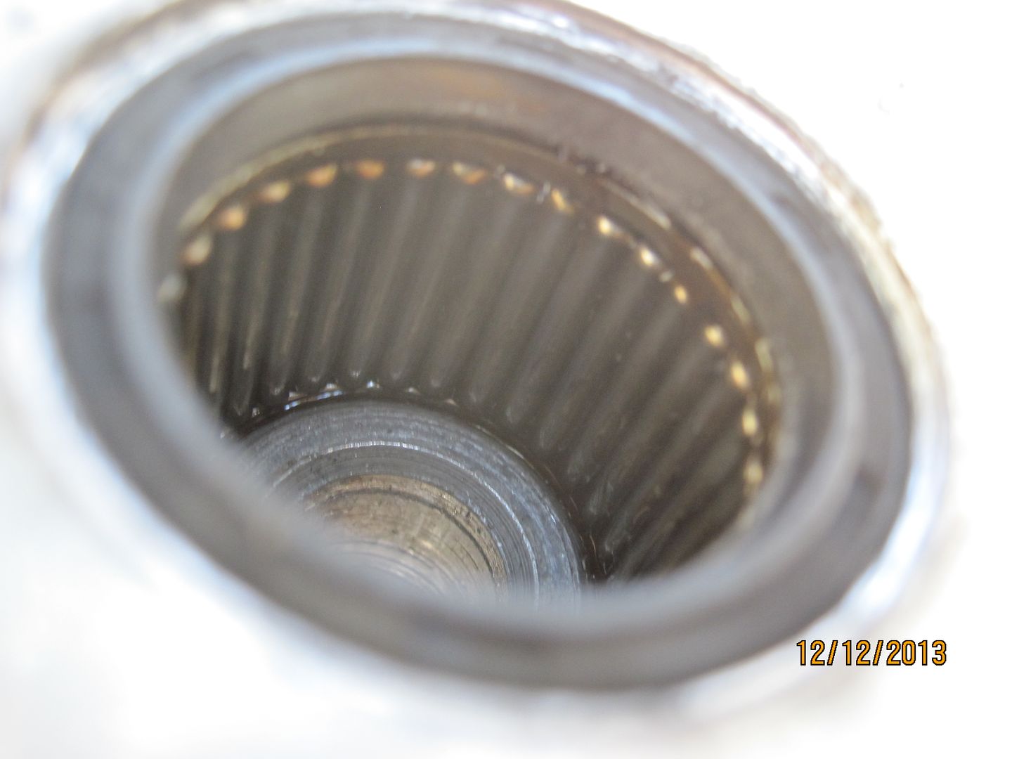
I then wiped those gearbox splines with some molybdenum grease.
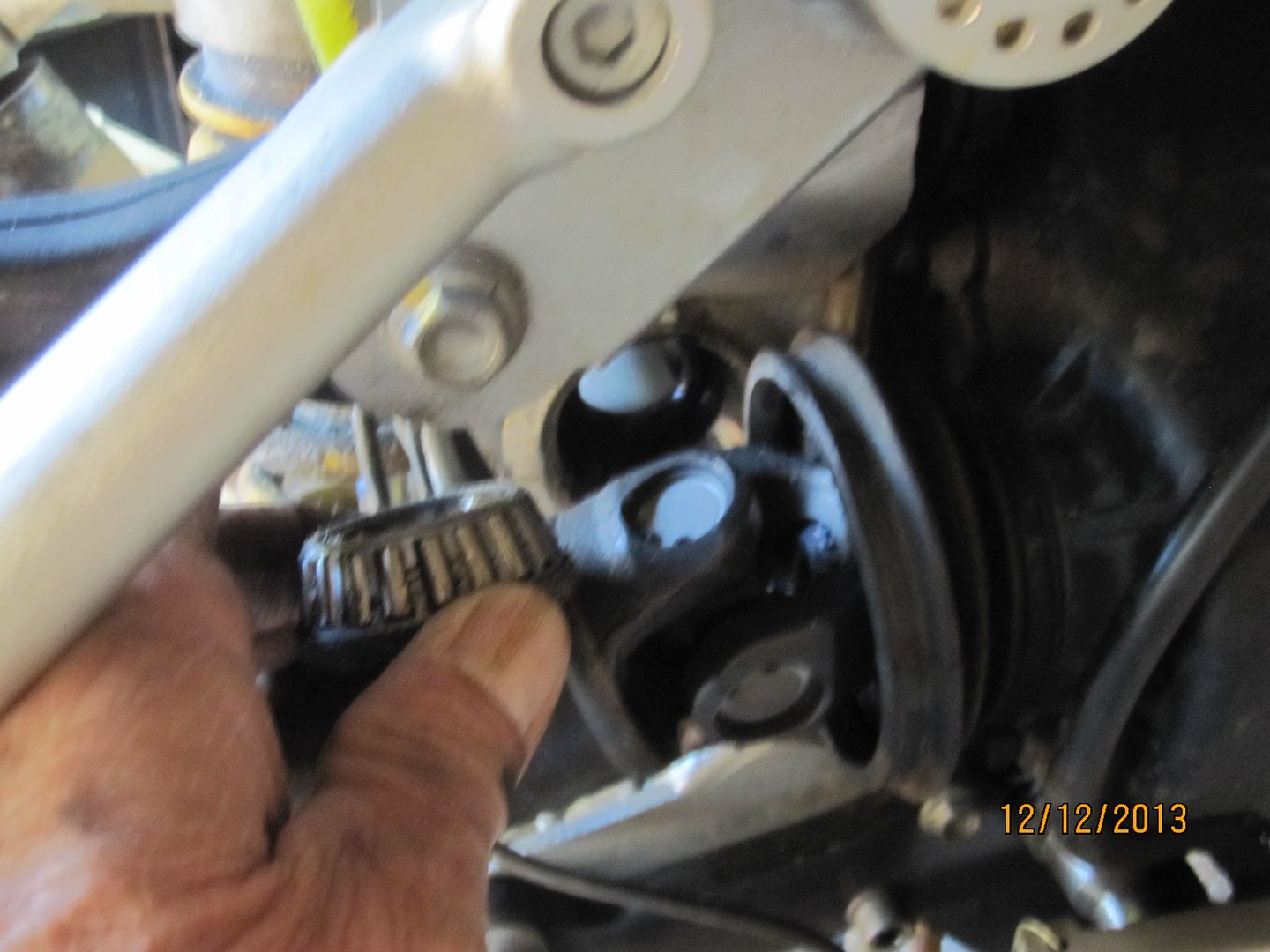
I also made a little side trip regarding the newly installed shock linkage dogbone as per the recent recall. I removed mine and inspected the needle bearings for grease. Again, only minimal grease was present in these bearings too. I added grease to all three bearings and reinstalled the linkage piece.
Next, the driveshaft was positioned and easily snapped on to the newly-greased output shaft in the same position from which it came. The shaft was then guided into the swingarm and the swingarm worked back into position on the frame over the newly-greased swingarm bearings.
The swingarm pin was cleaned and lightly greased.
At this point, the manual says to screw the preload bushing onto the swingarm pin and then insert the assembly through the frame holes to mount the swingarm. I found the job easier to first insert the swingarm pin and get it started in the threads on the right side of the swingarm and then thread the preload bushing onto the pin. Once this is done the pin can be tightened down to its 60 NM first and then the preload bushing tightened to its 10 NM. Having the castle nut tool is helpful when using a torque wrench for this adjustment. Using a conventional hook wrench would require tightening the castle nut snug to feel.
This is an interesting design. The pin screws into the swingarm's right side and is tightened to 60 NM. This does not put any preload on the bearings. The preload bushing on the left side is threaded onto the pin, into the pinch bore and up against the left side bearing. When the preload bushing is tightened to 10 NM, this puts proper preload on the both bearings. The pinch bolts are then tightened to hold the preload bushing in place.
With the swingarm reattached, a light bead of silicone type sealer was applied to the mating surface for the CARC, the CARC had its splines lightly greased and aligned to the driveshaft and repositioned on the swingarm.
The CARC final drive had its bolts tightened in a cross pattern to the specified 50 NM and all the items removed from the CARC reinstalled and properly torqued. The front boot was repositioned on the swingarm and secured with a new, commonly available, nylon tie. The control arm is attached at 50 NM. 50 NM for the brake caliper. The wheel lugs at 110 NM.
This is not a complicated job but being meticulous and cleaning everything will consume a lot of time. In the end, however, you'll have peace of mind that this job has been properly done. Now, I've got my mind on those steering head bearings.
Sorry for the date stamps on the images.
Before launching into this procedure, I consulted anecdotal accounts, other postings as well as the factory shop manual that leaves much to be desired.
I first removed the muffler to provide better access. By the way, it weighs about 18 pounds.

Next, the rear brake caliper was removed wrapped in protective plastic and set aside on the floor. The wheel was removed as was the ABS sensor, my tubing CARC, and all tubing was snapped out of the plastic retainers under the swingarm. Everything attached to the swingarm should be detached and laid aside. The control arm was then unbolted and tied up out of the way. Cut the big diameter nylon tie off the boot where the swingarm attaches to the transmission and pull the boot away from the swingarm.

I placed a wooden block under the CARC for temporary support.

The shock absorber link connection to the swingarm was then unbolted.

Next the final drive or CARC had its four bolts loosened but not totally removed. A piece of wood and a mallet was then used to gently rap the CARC loose from the sealer that had been used when it was previous bolted to the swingarm.

The 4 CARC bolts were then completely removed, the CARC easily pulled off and set aside. Though position of the driveshaft vis-à-vis the CARC is not critical, I marked my shaft ends since I wanted to later reconnect the shaft on the splines in the same position from where it came.

By the way, the CARC weighs 22.5 pounds.


Next, the two pinch bolts on the left side of the swingarm were loosened.

Then the special castle nut tool was used to remove the preload bushing. This bushing is tightened only to 10NM so it is easy to remove.

If you do not have the special castle nut tool, any adjustable hook wrench would work for removal.

The preload bushing is removed from the swingarm pivot pin and set aside. More on this part later.

Next, the swingarm pivot pin is removed with a large hex or Allen tool. My pin was not even finger tight and it should have 60 NM of torque.

The swingarm pivot pin is removed while steadying the swingarm with another hand.

The swingarm pivot pin.

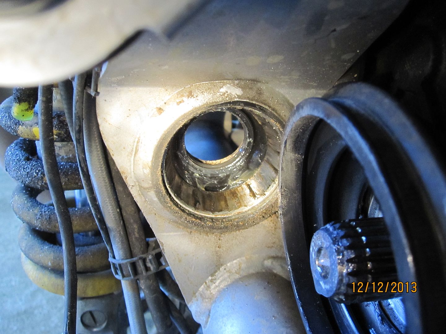
Next, leave the driveshaft attached and just easily work the swingarm out and off the driveshaft and set the swingarm aside.

Be careful not to lose this insert in the left side bore of the shock linkage bolt bore.


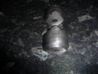
You do not have to actually remove the driveshaft to service the swingarm bearings. However, I wanted to wipe the splines of its connecting shaft with grease (none was there) so I removed the shaft. Using a drift on the U joint, a smart rap will release the shaft from the splines where it is retained by an internal spring clip. This procedure does not damage the the retaining clip so don't worry.


The swingarm itself weighs 7.5 pounds.

The driveshaft weighs 4.5 pounds. The total weight of the swingarm, shaft and CARC is 34.5 pounds.

You can see the bearing and its rubber seal here on the right side of the machine. The seals just pull out of a shallow bore and the bearings just fall out of their races.


My bearings had minimal grease. Thankfully, they cleaned up nicely and did not show permanent scars or marks.


Everything was cleaned-up. The bearings were packed with Teflon additive grease, the races wiped with the same and the bearings with seals positioned back into their bores. The seals were just fine but, in retrospect, I'd use new seals anyway.


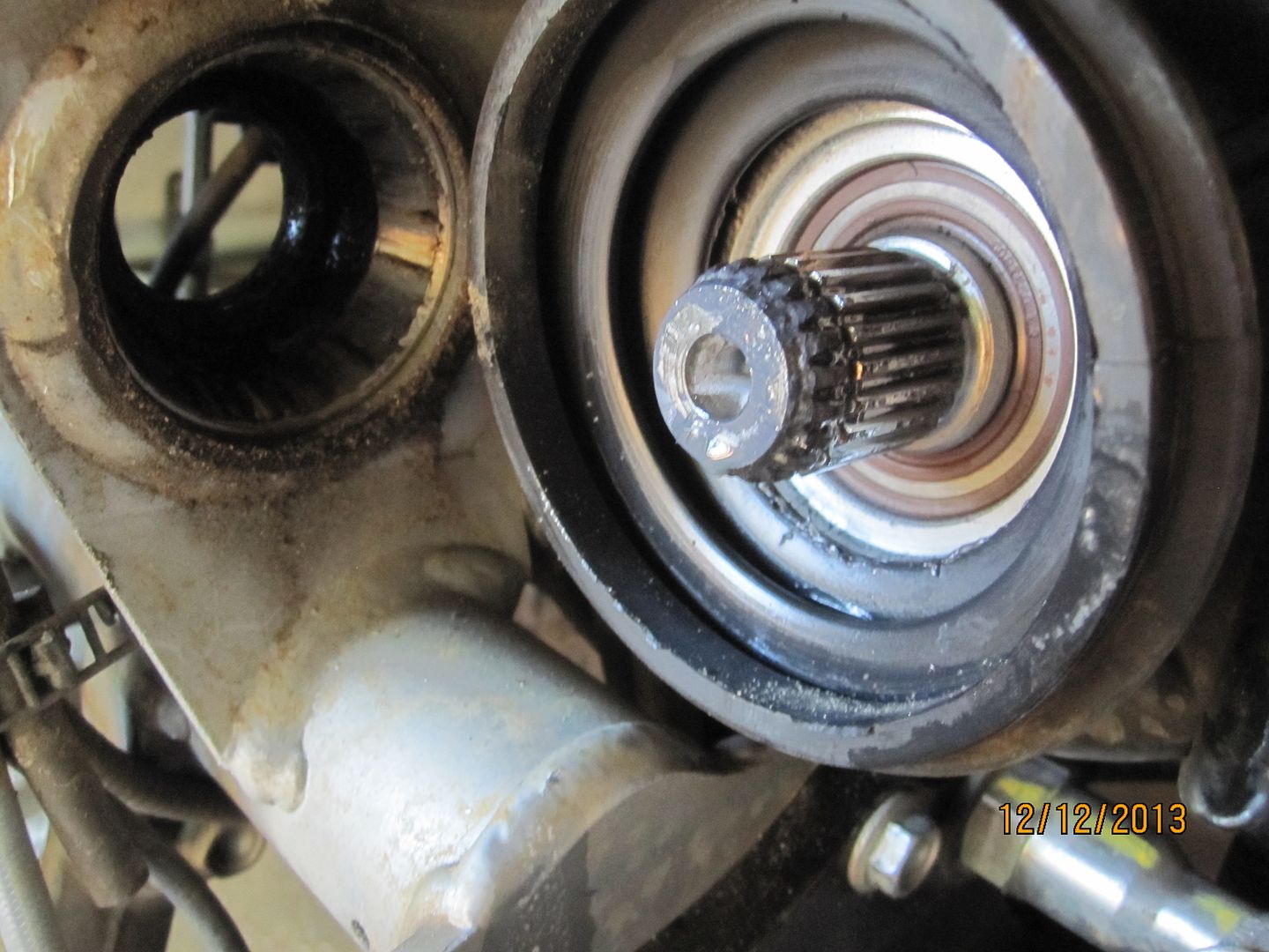
I then wiped those gearbox splines with some molybdenum grease.

I also made a little side trip regarding the newly installed shock linkage dogbone as per the recent recall. I removed mine and inspected the needle bearings for grease. Again, only minimal grease was present in these bearings too. I added grease to all three bearings and reinstalled the linkage piece.

Next, the driveshaft was positioned and easily snapped on to the newly-greased output shaft in the same position from which it came. The shaft was then guided into the swingarm and the swingarm worked back into position on the frame over the newly-greased swingarm bearings.


The swingarm pin was cleaned and lightly greased.

At this point, the manual says to screw the preload bushing onto the swingarm pin and then insert the assembly through the frame holes to mount the swingarm. I found the job easier to first insert the swingarm pin and get it started in the threads on the right side of the swingarm and then thread the preload bushing onto the pin. Once this is done the pin can be tightened down to its 60 NM first and then the preload bushing tightened to its 10 NM. Having the castle nut tool is helpful when using a torque wrench for this adjustment. Using a conventional hook wrench would require tightening the castle nut snug to feel.
This is an interesting design. The pin screws into the swingarm's right side and is tightened to 60 NM. This does not put any preload on the bearings. The preload bushing on the left side is threaded onto the pin, into the pinch bore and up against the left side bearing. When the preload bushing is tightened to 10 NM, this puts proper preload on the both bearings. The pinch bolts are then tightened to hold the preload bushing in place.


With the swingarm reattached, a light bead of silicone type sealer was applied to the mating surface for the CARC, the CARC had its splines lightly greased and aligned to the driveshaft and repositioned on the swingarm.

The CARC final drive had its bolts tightened in a cross pattern to the specified 50 NM and all the items removed from the CARC reinstalled and properly torqued. The front boot was repositioned on the swingarm and secured with a new, commonly available, nylon tie. The control arm is attached at 50 NM. 50 NM for the brake caliper. The wheel lugs at 110 NM.


This is not a complicated job but being meticulous and cleaning everything will consume a lot of time. In the end, however, you'll have peace of mind that this job has been properly done. Now, I've got my mind on those steering head bearings.