elfrider
Just got it firing!
Gday,
I'm finally trying to wire the AUX light to only come on when high beam is on.
I'd also like to be able to turn them off when high beam is on, i.e. I still want them wired through the AUX light switch on the right handle bar grip.
However, I'm having trouble trying to figure out the light logic.
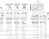
First of all the diagram below is for a MY11 Stelvio, I have a 2012 model, so not sure if the diagram is correct. The #65 relay I have is a five pin relay and has a middle 87a pin with black wire. The 30 pin on the #65 relay I have is BLACK/GREY but the diagram below says GREEN/WHITE. All the other pins are the colors as the diagram below.
I would of thought that disconnecting the WHITE/GREEN (position 3) wire from the #6 relay, blocking it off and 'piggy backing' the BLACK/WHITE (position 5) from the #65 relay and connecting it to position 3 on the #6 relay would of done the trick. Canuck was very helpful in pointing me in the right direction a few months ago with this.
However, as it turns out the YELLOW/BLACK (position 5) and WHITE/GREEN (position 3) on the #6 relay is powered (12v reading) when the light switch is off, the lights are also off. I still get a 12v reading across the two wires even with the key out of the ignition. When I start the bike and turn the AUX lights on, the voltage between the two drops to zero, circuit open? (but the lights are on)
I have tried disconneting the position 3 wire from #6 relay and piggy backing the 87 pin (position 5) from the #65 relay (as well as the 87a and 30 pin) but the AUX light didn't work as I would of expected, they didn't come on at all.
Has anyone successfully achieved what I'm attempting and get it to work? I'm obviously missing something here.
Any help would be appreciated.
Thanks guys.
The right hand indicator is disconnected at the moment to gain access to the relays but surely that shouldn't affect the circuit for the AUX/HB lights.

