Uss
Tuned and Synch'ed
Hello All,
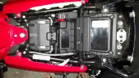
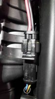
I have just received the MG USB Support kit 2S000166 & a set ofMG Crash Bars for my Eldo. The instruction sheet with the USB kit mentions how the one top end is to be connected but doesn't mention where exactly to find the connector end. I have attached a photo of the kit. If anyone has installed this on a Cali or an Eldo can you please advise where to find the connector on the bike?
Also on the Crash Bars are they fairly simple to install or is it better done by a workshop? How long would it take to assemble these?
Cheers