• Ciao Guest - You’ve landed at the ultimate Guzzi site. NEW FORUM REGISTRATIONS REQUIRE EMAIL ACTIVATION - CHECK YOUR SPAM FOLDER - Use the CONTACT above if you need help. New to the forum? For all new members, we require ONE post in the Introductions section at the bottom, in order to post in most of the other sections. ALWAYS TRY A SEARCH BEFORE STARTING A NEW TOPIC - Most questions you may have, have likely been already answered. DON'T BE A DRIVE-BY POSTER: As a common courtesy, check back in and reply within 24 hours, or your post will be deleted. Note there's decades of heavily experienced Guzzi professionals on this site, all whom happily give endless amounts of their VALUABLE time for free; BE COURTEOUS AND RESPECTFUL!
  • There is ZERO tolerance on personal attacks and ANY HYPERLINKS to PRODUCT(S) or other competing website(s), including personal pages, social media or other Forums. This ALSO INCLUDES ECU DIAGnostic software, questions and mapping. We work very hard to offer commercially supported products and to keep info relevant here. First offense is a note, second is a warning, third time will get you banned from the site. We don't have the time to chase repeat (and ignorant) offenders. This is NOT a social media platform; It's an ad-free, privately funded website, in small help with user donations. Be sure to see the GTM STORE link above; ALL product purchases help support the site, or you can upgrade your Forum profile or DONATE via the link above.
  • Be sure to see the GTM STORE link also above for our 700+ product inventory, including OEM parts and many of our 100% Made-in-SoCal-USA GTM products and engine kits. In SoCal? Click the SERVICE tab above for the best in service, tires, tuning and installation of our products or custom work, and don't miss our GT MotoCycles® (not) art on the BUILDS tab above. WE'RE HERE ONLINE ONLY - NO PHONE CALLS MADE OR RECEIVED - DO NOT EMAIL AND ASK QUESTIONS OR ASK TO CALL YOU.
  • Like the new V100, GuzziTech is full throttle into the future! We're now running on an all-new server and we've updated our Forum software. The visual differences are obvious, but hopefully you'll notice the super-fast speed. If you notice any glitches or have any issues, please post on the Site Support section at the bottom. If you haven't yet, please upgrade your account which is covered in the Site Support section or via the DONATE tab above, which gives you full site access including the DOWNLOADS section. We really appreciate every $ and your support to keep this site ad-free. Create an account, sign in, upgrade your account, and enjoy. See you on the road in 2024.

V7 Pull-up module resistor burned up

Stephan Schmitz-Justen

Just got it firing!
Joined
Jun 2, 2020
Messages
6
Location
Los Angeles, CA
Hey Guys!

New to the Forum and new to Guzzis! I just got a custom V7 and I am redoing some of the messy wiring the previous owner left behind and I stumbled upon a burnt up pull-up resistor as seen in the image below.

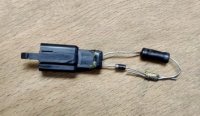
IMG 20200530 125034

F8B03FDB B213 45E0 9783 E1D76B65FDE1

When took it out of the heat shrink I could see that the part is simply a small diode and a larger resistor. The diode is fine and I was able to get a measurement of 220 Ohms from the resistor, but I believe this to be too little and I was not able to find the information on the resistance elsewhere on the web. Due to the resistor being burned, I cannot assume that the resistance is correct and cannot read the part number on the piece to look it up.

I do not wan't to pay the 50ish dollars for a new piece (Part number 887948) if I can replace just the resistor for maybe a dollar or two. I was wondering if anyone would be willing to look at their part and see if you can read the information on the resistor or measure it. If you cannot read it and have to measure it you would need to take off the heat shrink.

I think it would be great to have the information for the pull-up module on the forum so no one has to shell out 20x what it costs to make the part.
 
Kevin, it appears to be part of the clutch switch operation, and is simply a resistor and a diode in series. How they can justify €49.90 for a simple diode is beyond belief. This price doesn't include the series resistor either.

I'm guessing there might have been a short around the clutch switch or the side stand switch that caused excessive current to cook the resistor.

I can't identify what the device is between the resistor and diode, perhaps it's just a crude jointing mechanism.

I'd be heading to Radio Shack for replacements. 220Ω for the resistor seems credible to me.
 
From your second pic, the resistor doesn't look to me like it's "burned up". Perhaps it's good and it's supposed to be 220 ohms. I can see the melt hole or possibly abrasion hole in the overwrap plastic tubing, but that doesn't mean the resistor has actually overheated. BTW, at 12.5V, 220 ohms would dissipate 0.71W, enough to create some warmth. A 2W resistor would be appropriate.
 
New to the Forum and new to Guzzis! I just got a custom V7 and I am redoing some of the messy wiring the previous owner left behind and I stumbled upon a burnt up pull-up resistor as seen in the image below.
Hi Stephan, welcome to the GT Forum & Guzzi Famiglia. Assume LA County is Los Angeles based on your avatar, yes? If so, we have a solid Guzzi community here in SoCal. Hope you'll also add your info to our Registry; https://www.guzzitech.com/forums/threads/v7-registry-picture-thread-add-your-bike.9108

On that 887948 resistor, were you getting a check engine light or did you just stumble on it?
 
Hey guys,
thanks for the responses and warm welcome!

Looks like its a crude tubular crimp joint. As you say 220 ohms seems correct as resistors go "open or high" when abused.
It is indeed a crimp joint. At 220 Ohms you get about 50mA, which I believe to be a lot for a simple input switch. You usually see pull-up resistors in the 10k range, but maybe the Italians do it differently?

On that 887948 resistor, were you getting a check engine light or did you just stumble on it?
I just stumbled upon it. My bike sadly does not have the stock dash and has no check engine light. Once I have more of the wiring back together I will check if it is on.

From your second pic, the resistor doesn't look to me like it's "burned up". Perhaps it's good and it's supposed to be 220 ohms. I can see the melt hole or possibly abrasion hole in the overwrap plastic tubing, but that doesn't mean the resistor has actually overheated. BTW, at 12.5V, 220 ohms would dissipate 0.71W, enough to create some warmth. A 2W resistor would be appropriate.
Yeah definitely need to go with a 1-2W resistor. But I will also see what kind of resistance I get when measuring pin 14 and 19 to ground and I'll report back here. The resistor definitely had heat damage to it and it looks like it came from the resistor itself.

Thanks again for all the help guys!
 
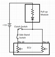
Made a little image to show what the circuit fully looks like.
Guzzi
Found this info online
"The value of the pull-up resistor needs to be chosen to satisfy two conditions:

  1. When the button is pressed, the input pin is pulled low. The value of resistor R1 controls how much current you want to flow from VCC, through the button, and then to ground.

  2. When the button is not pressed, the input pin is pulled high. The value of the pull-up resistor controls the voltage on the input pin.
For condition 1, you don't want the resistor's value too low. The lower the resistance, the more power will be used when the button is hit. You generally want a large resistor value (10kΩ), but you don’t want it too large as to conflict with condition 2.
The general rule for condition 2 is to use a pull-up resistor (R1) that is an order of magnitude (1/10th) less than the input impedance (R2) of the input pin. An input pin on a microcontroller has an impedance that can vary from 100k-1MΩ."

R2 would be the resistors in the ECU which should be easy to measure and then it'll be quick math and we have needed resistance.
 
Back
Top