• Ciao Guest - You’ve landed at the ultimate Guzzi site. NEW FORUM REGISTRATIONS REQUIRE EMAIL ACTIVATION - CHECK YOUR SPAM FOLDER - Use the CONTACT above if you need help. New to the forum? For all new members, we require ONE post in the Introductions section at the bottom, in order to post in most of the other sections. ALWAYS TRY A SEARCH BEFORE STARTING A NEW TOPIC - Most questions you may have, have likely been already answered. DON'T BE A DRIVE-BY POSTER: As a common courtesy, check back in and reply within 24 hours, or your post will be deleted. Note there's decades of heavily experienced Guzzi professionals on this site, all whom happily give endless amounts of their VALUABLE time for free; BE COURTEOUS AND RESPECTFUL!
  • There is ZERO tolerance on personal attacks and ANY HYPERLINKS to PRODUCT(S) or other competing website(s), including personal pages, social media or other Forums. This ALSO INCLUDES ECU DIAGnostic software, questions and mapping. We work very hard to offer commercially supported products and to keep info relevant here. First offense is a note, second is a warning, third time will get you banned from the site. We don't have the time to chase repeat (and ignorant) offenders. This is NOT a social media platform; It's an ad-free, privately funded website, in small help with user donations. Be sure to see the GTM STORE link above; ALL product purchases help support the site, or you can upgrade your Forum profile or DONATE via the link above.
  • Be sure to see the GTM STORE link also above for our 700+ product inventory, including OEM parts and many of our 100% Made-in-SoCal-USA GTM products and engine kits. In SoCal? Click the SERVICE tab above for the best in service, tires, tuning and installation of our products or custom work, and don't miss our GT MotoCycles® (not) art on the BUILDS tab above. WE'RE HERE ONLINE ONLY - NO PHONE CALLS MADE OR RECEIVED - DO NOT EMAIL AND ASK QUESTIONS OR ASK TO CALL YOU.
  • Like the new V100, GuzziTech is full throttle into the future! We're now running on an all-new server and we've updated our Forum software. The visual differences are obvious, but hopefully you'll notice the super-fast speed. If you notice any glitches or have any issues, please post on the Site Support section at the bottom. If you haven't yet, please upgrade your account which is covered in the Site Support section or via the DONATE tab above, which gives you full site access including the DOWNLOADS section. We really appreciate every $ and your support to keep this site ad-free. Create an account, sign in, upgrade your account, and enjoy. See you on the road in 2024.

Mysterious modification

j_hanna

Just got it firing!
Joined
Aug 26, 2012
Messages
1
Hello from Oklahoma,

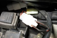
I've recently bought a used '08 Sport 1200 and found a connector under the seat that has been bypassed/looped back.

I bought the bike from a dealer a couple of states away who took the bike on trade so I can't contact the previous owner to ask about it. Everything on the bike appears to work correctly. It still has the canister setup so I wouldn't think it was part of that.
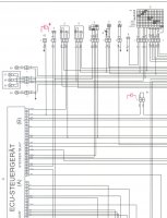
Found a wiring diagram online but wasn't able to figure it out, any clues?

Thanks in advance
 

Attachments

  • mystery.jpg
    mystery.jpg
    179.2 KB · Views: 1,059
I think that may be the antenna loop for the immobilizer circuit, that interacts with the RFID tag in the key.
 
I think it may be part of a Diag connector. Possible Dash/Instrument panel.

No. 60 on 2005 Breva 1100 Carl Allison wire diagram GIF. Don't think it's used as the smaller connector in the background is 60 but may share a wire or two.

Disconnect will disconnect ECU and bike will fail to start.
 
Spokes said:
I think it may be part of a Diag connector. Possible Dash/Instrument panel.

No. 60 on 2005 Breva 1100 Carl Allison wire diagram GIF. Don't think it's used as the smaller connector in the background is 60 but may share a wire or two.

Disconnect will disconnect ECU and bike will fail to start.
That makes it sound like a connector for an alarm system.
 
More like 61 on his diagram - Diode pre-setting whatever that means. The Guzzi diagram says Diode pre-intallation, which suggests it is a loop waiting for an addition.
 
Hello to all, i'll introduce myself because it's my first posting:
Living in the city of Villach, Austria, near the italian border (approx. 20 km). Age 58, married and riding a Breva 1100 - wife hates bikes :mrgreen:

Solution: There a two mysterious connectors with numbers 61 and 62 (Note: The numberings in the original schematic and in the keylist differ and are wrong).
Correct: 61-Diode pre-install, 62-Capacitor pre install, 63-Navi-Connector

Why diode and capacitor?
All the CARC-models have a battery voltage check, done by the ECU on its own +12V connector. If voltage is too low, the engine won't start. Everyone driving a CARC knows the "klack" :( - the starter motor needs a lot of current, a weak battery voltage breaks down an the ECU says "No!"

With the diode and a capacitor the ECU has it's own "buffered voltage source" independ from the voltage-breakdown while the starter motor works - you will never hear the "klack" again until the battery is finally broken down.
Do not use a simple silicone diode but take a schottky, such as SB5100 (5Amps, 100Volts) from Fairchild Semiconductor or similar.
Best for the capacitor is an electrolytic with 1000 - 2500 microfarad / 35 or 50 Volts.

Scheme: http://postimage.org/image/cyj8yay0z/

mandi
Gunther

My Brave :) - Northern Italy, Friuli Venezia Giulia, Alps between Sella di Razzo and Forcella di Lavardet


Forcella di Lavardet - only possible in Italy :S

 
Well, reading the trouble people had with this problem and after having talked of a similar solution for dash related trouble, I cannot see the reason the factory left these connectors unpopulated :S
They have placed the wiring there for this good-design-practise addition and then just did not source the proper diode and capacitor parts encapsulated up to automotive standards. It certainly looks like a mystery to me.

And it is getting even more mysterious when I see that the schematic part that Dormiglione posted above
(http://postimage.org/image/cyj8yay0z/) is present in the Griso 1100 (nr.8140904, 11/2005) but not in the Breva 1100 (nr.8140861, 07/2005), Griso 8V (nr.854378, 2007) and Stelvio NTX (nr.981138, 2009) english service manuals I went through. These have the line going straight to the battery node with no plugs for the diode and capacitor.
However they all state pretty much the same description for this ECU connection:
"pin 4 : Protected power supply from instrument panel".
for this line that comes from a battery connected node after the main fuses so it is "protected" but no relation seems to be to the instrument panel.

My theory is that some bean-counter accountant ordered to have this (right-minded) ECU power protection omitted as it is "good enough" as it is in relation to costs that were cut
OR they run into some bug trouble in relation to how the ECU interacted to the dash on power down and just preferred to cut the long debugging story short...
 

Attachments

  • ECU_Pufferung.jpg
    ECU_Pufferung.jpg
    138.3 KB · Views: 739
The schematic i added is out of Brevas V1100 service manual 854308, 12-2007.
I think the reason to "update" wiring was the implementation of ABS in 2006 because the block has an additional current consumption of app. 4 Amps and the "klack" problem grew disproportionately.

...i fully agree to your theory...

mandi
Gunther

PS: there is another cadaver in Guzzis CARC cellar, the fuel sensor which is very often defective - a horrible construction, suitable only for trash.
While Guzzis spareparts list holds only the "Fuel pump cpl" at a price of ~ 550 Euro it's possible to change the sensor separatly. Its the same as in Aprilia and has the sparenumber AP8127817 and a price of ~ 60 Euro.
 

Attachments

  • Tankanzeige.pdf
    328.7 KB · Views: 35
Dormiglione said:
The schematic i added is out of Brevas V1100 service manual 854308, 12-2007.
I think the reason to "update" wiring was the implementation of ABS in 2006 because the block has an additional current consumption of app. 4 Amps and the "klack" problem grew disproportionately.

4 amps consumption seems too big for the ABS unless you talk about consumption when it is activated.
Of course, 4 extra amperes could dip the ECU into shutdown territory and have the bike sputter or even die when the ABS is activated under heavy braking, that is exactly the time you need no extra balance disruption... Not to talk about catalysts disliking any sputter pressure pulses up to breaking into pieces to protest!
Also, I do not see this addition to the NTX 2012 manual that is the ABS model.
The ABS unit used could have some supercapacitor incoraparated to avoid messing the rest of the electrics upon activation, though I doubt it...
 
My Triumph Tiger 1050 had the same loop wire connector. It was for the factory alarm which would disable the engine if the alarm was triped. On my Norge, it made the anti hijack feature of the Scorpio alarm I installed as simple as cutting the loop and then adding a connector. It seams to be a European bike feature. I haven't seen it on any Japanese bikes.
 
Back
Top