• Ciao Guest - You’ve landed at the ultimate Guzzi site. NEW FORUM REGISTRATIONS REQUIRE EMAIL ACTIVATION - CHECK YOUR SPAM FOLDER - Use the CONTACT above if you need help. New to the forum? For all new members, we require ONE post in the Introductions section at the bottom, in order to post in most of the other sections. ALWAYS TRY A SEARCH BEFORE STARTING A NEW TOPIC - Most questions you may have, have likely been already answered. DON'T BE A DRIVE-BY POSTER: As a common courtesy, check back in and reply within 24 hours, or your post will be deleted. Note there's decades of heavily experienced Guzzi professionals on this site, all whom happily give endless amounts of their VALUABLE time for free; BE COURTEOUS AND RESPECTFUL!
  • There is ZERO tolerance on personal attacks and ANY HYPERLINKS to PRODUCT(S) or other competing website(s), including personal pages, social media or other Forums. This ALSO INCLUDES ECU DIAGnostic software, questions and mapping. We work very hard to offer commercially supported products and to keep info relevant here. First offense is a note, second is a warning, third time will get you banned from the site. We don't have the time to chase repeat (and ignorant) offenders. This is NOT a social media platform; It's an ad-free, privately funded website, in small help with user donations. Be sure to see the GTM STORE link above; ALL product purchases help support the site, or you can upgrade your Forum profile or DONATE via the link above.
  • Be sure to see the GTM STORE link also above for our 700+ product inventory, including OEM parts and many of our 100% Made-in-SoCal-USA GTM products and engine kits. In SoCal? Click the SERVICE tab above for the best in service, tires, tuning and installation of our products or custom work, and don't miss our GT MotoCycles® (not) art on the BUILDS tab above. WE'RE HERE ONLINE ONLY - NO PHONE CALLS MADE OR RECEIVED - DO NOT EMAIL AND ASK QUESTIONS OR ASK TO CALL YOU.
  • Like the new V100, GuzziTech is full throttle into the future! We're now running on an all-new server and we've updated our Forum software. The visual differences are obvious, but hopefully you'll notice the super-fast speed. If you notice any glitches or have any issues, please post on the Site Support section at the bottom. If you haven't yet, please upgrade your account which is covered in the Site Support section or via the DONATE tab above, which gives you full site access including the DOWNLOADS section. We really appreciate every $ and your support to keep this site ad-free. Create an account, sign in, upgrade your account, and enjoy. See you on the road in 2024.

160 Stornello electrical problem

osvaldo

Just got it firing!
GT Contributor
Joined
May 31, 2012
Messages
3
Hi guys,

I have got an old good 1974 Stornello that is giving me a lot trouble with the electric circuit.

It has been modified by the previous owner eliminating the battery and changing some connection on main switch.

Now as far as light is working very bad being as low as off when going slow and worst acting brake pedal.

I would like to get back to the original but first i would like to fully understand the logic of the original circuit.

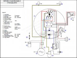
If I look at the original schematic (see picture) I get a bit confused mainly because is missing the internal schematic of the magneto and I can't really imagine how the switch is suppose to change connections in every position.

Has anybody ever look at the schematic and fully understood its logic?

If so, would he like to share his knowledge?

Thanks a lot for your attention

Osvaldo
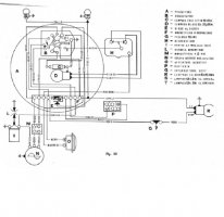
Immagine Immagine
 
Hi John,

I have done a small donation to the site and I'm waiting for the upgrade to download the schematic.
I suppose that should be something similar to these that I found in the net:

Stornello electrical

If so, let say it is a lot clearer than the original.
Only internal generator schematic missing and item 2 and 19 are in one block only on the motorbike.
Hoping I'm not boring you let see if I understand something:
Item 19, quite simple, pushing down the key, from off to on, disconnect from the ground the gray generator cable from the ignition coil enabling it.
In the mean time connect the negative pole of the battery to the frame (ground).
Horn and stop light are enabled if you push their switch.
Is that correct?
Now let see item 2.
I know that green and red cables from generator come from two different point of the same coil, giving different voltage; let say around 3.000 rpm 16 V the green and 8 V the red.
With key on, centre position engine running, green charge the battery trough blue passing a diode.
Since current from the diode is just half wave 16V seems to be more or less correct for the task.
Same if you turn key to the right.
I suppose upper part of the rotor in the main switch turn together with the lower and is always connected with the yellow cable.
If so, turning key to right we light trough black and yellow cable, front and rear city light plus instrument if there are.
If we turn key to the left we switch off front city light ad send current to hi/low beam, depending on the position of external switch.
Up to now a I correct?
But what about battery? If we pass trough a single diode an 8V AC are we going to have enough voltage to charge the battery?
Plus in the previous case current come from fuse and can be aided from battery, while in this case it seems that can be charged only.
It can not supply current do the unidirectional diode and the light are totally dependent on alternator.
Where am I wrong?

Best Regards
Osvaldo

(BTW escuse me for my english)
 
Both schematics are very similar and the same mistakes on the battery and horn identification. From the schematic the battery should be 6 volt, as ther are only 3 cells. Also it appears 2 and 19 are mislabeled. The spark is available when the magneto isn't grounded. As soon as you ground the magneto, spark stops.
 
Here is my interpretation of the circuit:
1. The negative terminal of the 6V battery is not solidly grounded to the frame. It is grounded when the key is inserted to complete the circuits for the lights, horn, and charging.
2. The ground of the ignition is opened when the key is inserted to allow spark. The coil is grounded when the key is removed to stop the engine.
3. The green and red wires are both charging outputs from the generator (magneto). There is no voltage regulator to avoid overcharging the battery (just the diode to provide half wave rectified charging current).
4. The green wire is connected to the diode to charge the battery at a lower voltage (lower current) when the headlight is not turned on. This should help keep the battery from being overcharged.
5. The red wire is connected to the diode to charge the battery at a higher voltage (higher current) when the headlight is on either low beam or high beam. This should provide enough charging current to charge the battery and keep the headlight bright.
6. The yellow wire provides power to the taillight, speedometer light, and tachometer light in either switch position.
7. The top contact of the switch selects either the headlight or the city light.
8. The bottom contact of the switch selects the charging output. Green is connected to blue for low charge rate when headlight is not on. Red is connected to blue for high charge rate when headlight is on.
 
Back
Top