• Ciao Guest - You’ve landed at the ultimate Guzzi site. NEW FORUM REGISTRATIONS REQUIRE EMAIL ACTIVATION - CHECK YOUR SPAM FOLDER - Use the CONTACT above if you need help. New to the forum? For all new members, we require ONE post in the Introductions section at the bottom, in order to post in most of the other sections. ALWAYS TRY A SEARCH BEFORE STARTING A NEW TOPIC - Most questions you may have, have likely been already answered. DON'T BE A DRIVE-BY POSTER: As a common courtesy, check back in and reply within 24 hours, or your post will be deleted. Note there's decades of heavily experienced Guzzi professionals on this site, all whom happily give endless amounts of their VALUABLE time for free; BE COURTEOUS AND RESPECTFUL!
  • There is ZERO tolerance on personal attacks and ANY HYPERLINKS to PRODUCT(S) or other competing website(s), including personal pages, social media or other Forums. This ALSO INCLUDES ECU DIAGnostic software, questions and mapping. We work very hard to offer commercially supported products and to keep info relevant here. First offense is a note, second is a warning, third time will get you banned from the site. We don't have the time to chase repeat (and ignorant) offenders. This is NOT a social media platform; It's an ad-free, privately funded website, in small help with user donations. Be sure to see the GTM STORE link above; ALL product purchases help support the site, or you can upgrade your Forum profile or DONATE via the link above.
  • Be sure to see the GTM STORE link also above for our 700+ product inventory, including OEM parts and many of our 100% Made-in-SoCal-USA GTM products and engine kits. In SoCal? Click the SERVICE tab above for the best in service, tires, tuning and installation of our products or custom work, and don't miss our GT MotoCycles® (not) art on the BUILDS tab above. WE'RE HERE ONLINE ONLY - NO PHONE CALLS MADE OR RECEIVED - DO NOT EMAIL AND ASK QUESTIONS OR ASK TO CALL YOU.
  • Like the new V100, GuzziTech is full throttle into the future! We're now running on an all-new server and we've updated our Forum software. The visual differences are obvious, but hopefully you'll notice the super-fast speed. If you notice any glitches or have any issues, please post on the Site Support section at the bottom. If you haven't yet, please upgrade your account which is covered in the Site Support section or via the DONATE tab above, which gives you full site access including the DOWNLOADS section. We really appreciate every $ and your support to keep this site ad-free. Create an account, sign in, upgrade your account, and enjoy. See you on the road in 2024.

2012+ NTX Lighting Relay Logic

canuck1969

GT Reference
GT Contributor
Joined
May 31, 2012
Messages
1,242
Location
Burlington, Ontario
There have been a few issues lately that involved the lighting relay. Mainly, if the lighting relay fails, you will loose your headlights (makes sense) and you will also loose your generator as the same relay supplies power to the exciter circuit for the generator. This has been proven both practically and laid out on the wiring diagram as such. The power from the lighting relay (ie. when it is triggered) also supplies power to the high beams when that relay is triggered buy the switch.

Here is where I get confused and hoping someone out there can answer the questions. There have been a couple of cases of the highbeams coming on with the switch and then when the switch is returned to low beam, the lights don't come on. This is were the lighting logic on the diagram breaks down (at least for me). Some have pointed to the relay being the cause, but it can't be since the lighting relay runs the generator and supplies power for the low beams and high beam relay. If you lost the lighting relay, you will loose all lighting and the generator.

What this all means is that when the high beam is selected, the highbeam relay triggers (same power source from the lighting relay output) and the high beams come on. At the same time, the low beams come off. Were in the wiring diagram does the low beam turn off when the high beams turn on. It can't be in the lighting relay because you will then loose everything. Is it in the LB/HB switch, or is the wiring diagram wrong. Has to be in the switch which makes the only sense but the drawing does not show that.
 
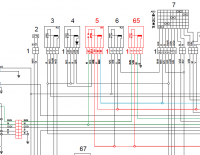
I´ve a wiring diagram for my my11 Stelvio. What i do not see , is a power supply from relay 5 (LB) to relay 65 (HB)
So, if the lightingrelay (5) fails ,you can use the HB (relays 65) whenever you pull the switch.
The only mistake in the diagram is: I only see the right HB bulb suported by the HB-Switch.

On my Stelvio both HB bulbs are on (european model)

Greetings
Steve
 
Last edited:
I´ve a wiring diagram for my my11 Stelvio. What i do not see , is a power supply from relay 5 (LB) to relay 65 (HB)
So, if the lightingrelay (5) fails ,you can use the HB (relays 65) whenever you pull the switch.
The only mistake in the diagram is: I only see the right HB bulb suported by the HB-Switch.

On my Stelvio both HB bulbs are on (european model)

Greetings
Steve

That one is there. It is 30 wire on relay 5 and 3 wire on 65. It is supplied by the famous 30 amp fuse. The trigger for 65 is controlled from the HB switch. That logic I can follow. just not how the LB turns off with the HB turns on.

You are correct on the HB only supplying the right side on the diagram. Mine HB also lights on both sides so there are some things missing from this diagram.

Upload 2014 10 17 14 25 36
 
I see now....you meant the main supply, this is correct. The diagram says that all bulbs are on when triggering relay 65.
As i remember, i have all the 230W when i push the HB-switch.I will check tomorrow. It is late here.
Steve
 
I see now....you meant the main supply, this is correct. The diagram says that all bulbs are on when triggering relay 65.
As i remember, i have all the 230W when i push the HB-switch.I will check tomorrow. It is late here.
Steve

And that is the puzzle. At least on mine, when you turn on the HB, the LB kicks out. Makes sense as it would probably melt everything and be too bright. But where the heck is it in the logic. The lighting relay can't kick out as the main power coming from the relay also powers the exciter on the alternator. If the relay kicked out every time the HB's came on, your alternator would stop producing power. There has to be another circuit between the LB/HB switch and the LB lights after the power leaves the lighting circuit.

Hate not know where it is because the day will come that something goes wrong and we will be chasing our tails. I don't think H4 bulbs have internal switches so when the HB side gets power, it drops the LB side???
 
Gents,
Been following your debate, I have had the same problem twice with my (2011 NTX) switching from high to low and loosing low beam, changed the relay both times, latest has been reliable.

I noticed on the wiring diagram, relay 65 there's a earth wire, would a bad earth effect the relay.

Marshy.

Which relay did you switch The lighting relay (5) or HB relay (65). May add to take away from the mystery

And yes, a bad ground on the HB relay would mean that it would not trigger the HB. But from the logic on the diagram, it should do nothing to the LB.
 
Which relay did you switch The lighting relay (5) or HB relay (65). May add to take away from the mystery

And yes, a bad ground on the HB relay would mean that it would not trigger the HB. But from the logic on the diagram, it should do nothing to the LB.

I replaced number 5 (5 pin) both times, i did think at first it was the handle bar switch, but when replacing relay everything was OK.

marshy.
 
Bugging me enough that I finally went out to the garage, exposed the relays and figured out the logic....at least to the point that I can now see what is going on.

The HB relay is actually a 5 pin relay with a nomally closed terminal (ie. 5th pin supplies power when it is not triggered). The drawing shows this as a 4 pin and this is where the logic for the LB lies.

When you start the bike, the lighting relay triggers and sends power to the alternator exciter and to the HB Relay. Power is then rerouted to the LB lights through the normally closed terminal on the HB relay. It is a black wire on the 5th terminal which is the same colour as the wire that supplies power to the LB. When you turn on the HB (either Pass or full on), the HB relay triggers, drops the power to the black wire and therefore the LB lights. The lighting relay does not turn off (as was suspected). Power is then supplied to the HB lights from the HB relay.

Only thing I need to look at is the logic of how the HB/LB switch works. I can't believe that the full power route through the swtich so the switch must only trigger the HB relay.

This means if you have a problem with the LB not coming on but HB working, it is most likely the HB relay, not the LB relay or even the switch. If the switch failed, in a failed state, the HB relay would not fire and you would still have LB, just no LB. I need to think the switch part through but I am pretty sure it has nothing to do with no LB with HB working.
 
Last edited:
Cannuck,

We'le follow your exploits with interest, sometimes the only but best way to go, "hands on".

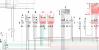
Mines the same, two 5 pin relays, out of interest the Norge 1200 v8 wiring diagram shows two 5 pin relays, nearly the same set up.
 
Marshy...that's it. You have found the missing link.

The lighting logic on the Norge is exactly what I found when I metered out the relay connections.

The lighting relay provides main power when triggered to the HB relay and also the alternator exciter circuit. The normally closed terminal on the HB relay runs power to the LB lights. Once you flick the HB switch, the HB relay triggers, the normally closed switches off (open, and therefore your LB lights) and the HB lights come on via the triggered normally open side of the switch (now closed and sending power to the HB lights). The switch only triggers the HB relay which makes sense since you don't want to be sending full lighting amps through the bar switch.

On the Stelvio, Relay 65 should really be called the HB/LB relay as it is on the Norge since that is it purpose.

So for those that have an issue with the LB lights not coming back on when you flip from HB to LB, may want to check the HB relay which is a 5 pin and not a 4 pin as indicated on the wiring diagram.

In the attached, the #6 relay is the lighting relay and #5 is the HB/LB relay. Attached the Norge Diagram for reference.

Now I can go enjoy my weekend.....and buy some spare relays since now that I figured out how it all works, it will probably not work any more.

Upload 2014 10 17 20 33 54
 

Attachments

  • Norge1200GT8V_WiringDiagram.pdf
    526.9 KB · Views: 47
Good Job all, congrats. I`ve tried to correct the diagram (in paint)
aybizmkx.jpg
 
Last edited:
My Stelvio is sitting at a dealer waiting for replacement LB and HB relays. Are these a Guzzi specific part or should I be able to source them at an auto electrics store?

Cheers
 
They are not Guzzi specific. They are both 5pin relays. Just need to find the same pin arrangement. Pretty sure a bosch relay should fit. Go get the old one and bring it to a parts store.
 
Well done all on this! :clap:

Just read through this post and it all sounds good but to us lesser mortals who don't have the electrical knowledge to follow what has been said we are eternally grateful for your time and trouble on this post!:whew:
 
Thanks. Im I looking for a change over relay or a normally open one? 30A?

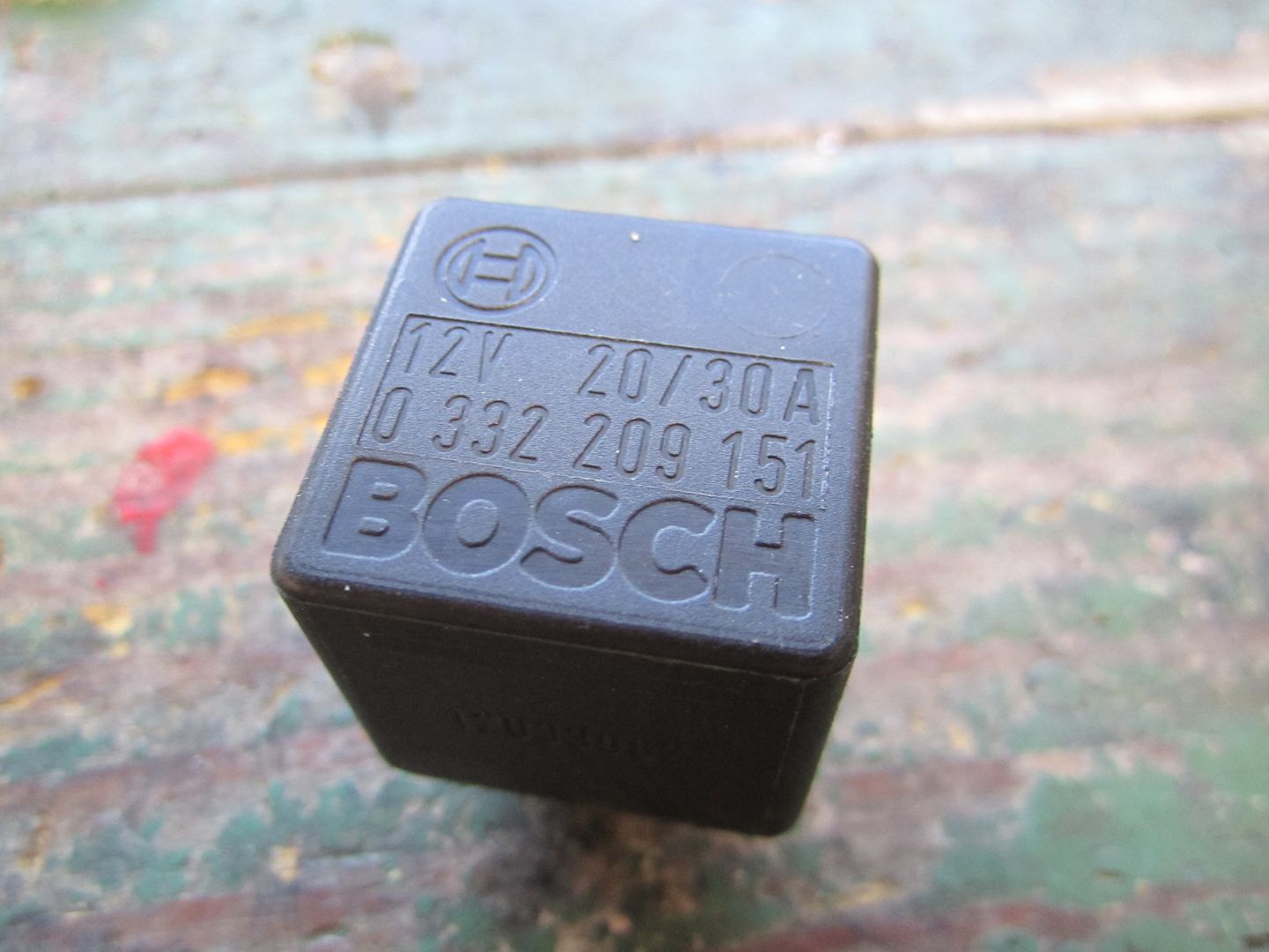
Another member has graciously posted a picture of the bosch relay. This should be enough for any auto parts guy to get it or cross reference it for you. I know they are readily available on ebay. Failing that, try a BMW or Mercedes dealer. Looks like they are used a lot on those brands.

A 5 pin relay will have one normally open and one normally closed switch terminal.

IMG_3692.jpg
 
That is a very common relay, Canuck. Mine are genuine Bosch but they sold out to Tyco who now produces them. The Tyco should be top quality. Many, many other brands are out there, some good, some bad. You can normally find them at most auto parts stores.

Check into my warning light and voltmeter installation described elsewhere. It can be a lifesaver!

Remember, you helped me 2+ years ago when my main fuse popped and nobody knew where it was? Everybody said it was under the seat! lol

I've been to Stelvio Electrics School since then - out of necessity!
 
Back
Top