• Ciao Guest - You’ve landed at the ultimate Guzzi site. NEW FORUM REGISTRATIONS REQUIRE EMAIL ACTIVATION - CHECK YOUR SPAM FOLDER - Use the CONTACT above if you need help. New to the forum? For all new members, we require ONE post in the Introductions section at the bottom, in order to post in most of the other sections. ALWAYS TRY A SEARCH BEFORE STARTING A NEW TOPIC - Most questions you may have, have likely been already answered. DON'T BE A DRIVE-BY POSTER: As a common courtesy, check back in and reply within 24 hours, or your post will be deleted. Note there's decades of heavily experienced Guzzi professionals on this site, all whom happily give endless amounts of their VALUABLE time for free; BE COURTEOUS AND RESPECTFUL!
  • There is ZERO tolerance on personal attacks and ANY HYPERLINKS to PRODUCT(S) or other competing website(s), including personal pages, social media or other Forums. This ALSO INCLUDES ECU DIAGnostic software, questions and mapping. We work very hard to offer commercially supported products and to keep info relevant here. First offense is a note, second is a warning, third time will get you banned from the site. We don't have the time to chase repeat (and ignorant) offenders. This is NOT a social media platform; It's an ad-free, privately funded website, in small help with user donations. Be sure to see the GTM STORE link above; ALL product purchases help support the site, or you can upgrade your Forum profile or DONATE via the link above.
  • Be sure to see the GTM STORE link also above for our 700+ product inventory, including OEM parts and many of our 100% Made-in-SoCal-USA GTM products and engine kits. In SoCal? Click the SERVICE tab above for the best in service, tires, tuning and installation of our products or custom work, and don't miss our GT MotoCycles® (not) art on the BUILDS tab above. WE'RE HERE ONLINE ONLY - NO PHONE CALLS MADE OR RECEIVED - DO NOT EMAIL AND ASK QUESTIONS OR ASK TO CALL YOU.
  • Like the new V100, GuzziTech is full throttle into the future! We're now running on an all-new server and we've updated our Forum software. The visual differences are obvious, but hopefully you'll notice the super-fast speed. If you notice any glitches or have any issues, please post on the Site Support section at the bottom. If you haven't yet, please upgrade your account which is covered in the Site Support section or via the DONATE tab above, which gives you full site access including the DOWNLOADS section. We really appreciate every $ and your support to keep this site ad-free. Create an account, sign in, upgrade your account, and enjoy. See you on the road in 2024.

Break light hookup.

oldmanjob

Cruisin' Guzzisti
Joined
Aug 24, 2009
Messages
271
Location
Dana NC
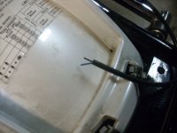
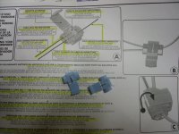
I have installed the brake light kit for the E30 Tour top case from Givi. All i have left to do is to connect it to the break light wire. Has any one done this, as even with parts list and wiring diagram I do not have a clue what to do as it seems the wires are in between the rear fender and the fender brace. The directions from Givi are as clear as mud. And my old brain has trouble processing things :eek: :shock: :lol: :lol:

Bill
 
Hmm, looking at Carl Alison's wiring diagram for the V7 Classic (http://www.thisoldtractor.com) it looks like switched power is applied to the rear tail light and stop light via a yellow wire. The return path for the stop light is via green/yellow wire to the front and rear brake switched wired in parallel. I'm assuming this wiring diagram applies to your bike.

Hopefully, the Givi kit offers two wires for connection to the integral stop light, offering an isolated ground connection. As long as this is the case, just connect one wire (the one considered the "hot" side) to the yellow wire, and the other to the green/yellow wire. I like those insulation displacement connectors that straddle the wire you want to hook into, and cut through the insulation when they close up; you can buy them at Radio Shack.

Because the V7 uses a conventional dual filament bulb, there should be no need to include a steering diode.
 
Yes there are 2 wires with the Givi wiring set up and they include 2 insulation displacement connectors :D 
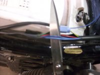
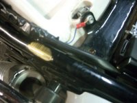
Now I just have to find the yellow wire :lol: Thanks for the reply.

Bill
 
If you've got both brake- and backlight in there, you'll probably (no, you WILL) need a 3rd wire for earth/frame/ground, whatever you call it.
 
There are just two wires , one for the break light and one ground, plus they supply 2 block clamps and according to the directions in 27 different languages one is for the hot and the other is for the ground :D They do not specify which color is which, so i would guess the black would be hot and the lighter one would be the ground :?

Bill
 

Attachments

  • DSCN1529.JPG
    DSCN1529.JPG
    169.9 KB · Views: 590
  • DSCN1530.JPG
    DSCN1530.JPG
    220.2 KB · Views: 590
oldmanjob said:
There are just two wires , one for the break light and one ground, plus they supply 2 block clamps and according to the directions in 27 different languages one is for the hot and the other is for the ground :D They do not specify which color is which, so i would guess the black would be hot and the lighter one would be the ground :?

Bill

Bill usually black is the Ground,negative, earth and the lighter color is the hot, positive , If the lights in the Givi are incandescent it wont matter, if they are leds it will they wont work if the polarity is reversed, just reverse your leads you will not hurt them if you hook it up wrong.
 
I don't recommend the use of block clamps for wiring. The wires remain open to atmosphere and the clamp becomes a point of corrosion. Also the block clamp may cut some of the wires reducing their ability to handle current. Better to solder in a two contact pigtail to the bike, and onto the new break light wire.
 
oldmanjob said:
There are two blue in the harness one dark and one light which is the ground :?:


That matches up to the left turn signal in the wiring diagram you might be in the wrong harness.

The right turn signal is Red and Blue, keep looking.

Stop light wire should be Green / Yellow
 
oldmanjob said:
These are the two blue wires :?
Hi Bill,

It would be the Dark Blue ....... (B) on the diagram is considered the ground
The light blue is for the left turn signal identified as (Az) Sky Blue on the diagram.
and Red is for the right turn.

Just a comment ..... As John mentioned soldering the wires would be perferable (Vibration, corrosion, etc).
Cheers
 
Bill, you do not want to connect to any ground point on your bike's wiring loom. The Givi case should get a connection to the switched positive yellow wire (via the ignition key), and the switched ground yellow/green wire (via either of the brake switches). A direct ground connection is not required.

Although it doesn't probably matter, I would determine which color wire in the Givi case is connected to the hot or center pin and make this wire the one that connects to the yellow wire. This just keeps the volts appearing at the bulb socket in the top box oriented in the traditional way.
 
Well I got it hooked up and it is working fine. I did ground it to the bike as I am not much with dealing with bike wiring and i did not want to mess anything up. And thanks for everyone's help :D
Bill
 

Attachments

  • DSCN1533.JPG
    DSCN1533.JPG
    182.4 KB · Views: 350
Back
Top