• Ciao Guest - You’ve landed at the ultimate Guzzi site. NEW FORUM REGISTRATIONS REQUIRE EMAIL ACTIVATION - CHECK YOUR SPAM FOLDER - Use the CONTACT above if you need help. New to the forum? For all new members, we require ONE post in the Introductions section at the bottom, in order to post in most of the other sections. ALWAYS TRY A SEARCH BEFORE STARTING A NEW TOPIC - Most questions you may have, have likely been already answered. DON'T BE A DRIVE-BY POSTER: As a common courtesy, check back in and reply within 24 hours, or your post will be deleted. Note there's decades of heavily experienced Guzzi professionals on this site, all whom happily give endless amounts of their VALUABLE time for free; BE COURTEOUS AND RESPECTFUL!
  • There is ZERO tolerance on personal attacks and ANY HYPERLINKS to PRODUCT(S) or other competing website(s), including personal pages, social media or other Forums. This ALSO INCLUDES ECU DIAGnostic software, questions and mapping. We work very hard to offer commercially supported products and to keep info relevant here. First offense is a note, second is a warning, third time will get you banned from the site. We don't have the time to chase repeat (and ignorant) offenders. This is NOT a social media platform; It's an ad-free, privately funded website, in small help with user donations. Be sure to see the GTM STORE link above; ALL product purchases help support the site, or you can upgrade your Forum profile or DONATE via the link above.
  • Be sure to see the GTM STORE link also above for our 700+ product inventory, including OEM parts and many of our 100% Made-in-SoCal-USA GTM products and engine kits. In SoCal? Click the SERVICE tab above for the best in service, tires, tuning and installation of our products or custom work, and don't miss our GT MotoCycles® (not) art on the BUILDS tab above. WE'RE HERE ONLINE ONLY - NO PHONE CALLS MADE OR RECEIVED - DO NOT EMAIL AND ASK QUESTIONS OR ASK TO CALL YOU.
  • Like the new V100, GuzziTech is full throttle into the future! We're now running on an all-new server and we've updated our Forum software. The visual differences are obvious, but hopefully you'll notice the super-fast speed. If you notice any glitches or have any issues, please post on the Site Support section at the bottom. If you haven't yet, please upgrade your account which is covered in the Site Support section or via the DONATE tab above, which gives you full site access including the DOWNLOADS section. We really appreciate every $ and your support to keep this site ad-free. Create an account, sign in, upgrade your account, and enjoy. See you on the road in 2024.

ECU location and removal

GTM®

Administrator
Staff member
GT di Razza Pura
Joined
Jul 1, 2009
Messages
15,134
Location
Malibu
Thanks to Al for the words and pics...

1. Disconnect the negative lead of the battery.

Options are remove the right side body work (a real pain) or work patiently from above and below to remove the ECU with the body work in place (less time and difficulty but you still need lots of patience)

2. Tools I used ( 1/4" socket drive, ext, 8mm socket, 4mm allen wrenches, lock grips, flashlight):

StelvECU-Tools.jpg


3. Top shot of the ECU which is forward on the left side of the bike, opposite the fuse/relay box. Note the mounting bolt nut at forward lower corner. There are two of these, another towards the back of the bike.

StelvECU-fromtop.jpg


4. Socket and extension on the nut:

StelvECU-Socketonnut.jpg


Both nuts were taken off with some difficulty as there is not much room to get to the allen head on the opposite side and hold it in some way while you are taking the nut off. The small vise grips were instrumental in this.

5. View of ECU from underneath after both bolts were removed:

StelvECU-boltsout.jpg


6. View from top of ECU with one of the electronic connectors removed. Both connectors are on the top. Study them carefully with good light. There is a small plastic tab on the top of the connector you can push down with a small flat tip screw driver and then rotate the connector lock down towards that tab to release the connector:

StelvECU-oneconnoff.jpg


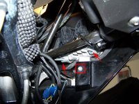
7. View from below of the released electronic connector and the most forward mounting bolt - note the ground wire on that mounting bolt:

StelvECU-conn-bolt-grdwire.jpg


8. Here is a shot of the ECU out of the bike with the mounting bolts:

StelvECU-out.jpg


It took me 60 - 90 minutes once I decided how to attack.
 
GT-Rx said:
It took me 60 - 90 minutes once I decided how to attack.

It took me twice as long, and if I had it to do all over again, I'd try another method of attack!

I had to use needlenose pliers to get at those bolts; I couldn't get an allen wrench in there. And it helped to undue some of the rip ties, so I could get the wires out of the way.

When I re-assemble, I was thinking I'd use different bolts (i.e. the type you can put a regular wrench on the end of) and maybe replace the lock nuts with something easier to take on and off.

Also, if it weren't for the fact that I can't get my side panels off (long story), I'd try attacking the ECU by first removing the panels....
 
I think this method would be much easier if the insturment panel was removed first. 4 Screws and one connector, take a couple of minutes. Of course the windshield should be off also.
 
Did the procedure a couple of time within a week or so. Not to bad, just requires patience, reading glasses if you have em, good light and the hand of your 12 year old son!!
 
If I may make an addition to this procedure ......
For the front bolt of the ECU you can gain better access, with the allen key, when removing (only one) front 3mm allen screw holding the LH silver duct.

(Looking at View #5, of this procedure, its the allen screw slightly below and between the 2 arrows)

On my 2009 doing so the allen key can be inserted through the port hole of the LH turn indicator.

By the way good procedure ... did it a couple of times also. Thanks Al
 

Attachments

  • StelvECU-boltsout.jpg
    StelvECU-boltsout.jpg
    59.7 KB · Views: 1,430
The 2012 Stelvio's have the ECU mounted with the connectors on the bottom, piece of cake to remove,my 1st time and it took me less than 10 min.
 
charlietuned said:
Hi , What ECU unit has the 2012 Stelvio NTX got ??
Still a 5AM. I've done several with great results.
 
Brian UK said:
If you have the ECU off, it might be a good time to fit the rubber waterproofing boot now available from Guzzi for a couple of bucks.

Does anybody have a part number for this waterproofing boot?

Thank you in advance.
 
scottmastrocinque said:
Brian UK said:
If you have the ECU off, it might be a good time to fit the rubber waterproofing boot now available from Guzzi for a couple of bucks.

Does anybody have a part number for this waterproofing boot?

Thank you in advance.

Not sure this boot is needed on the 2012 NTX's. The previous models had the ECU mounted with the connectors facing up, ours has it with the connectors facing down (at least on mine).
 
scottmastrocinque said:
Brian UK said:
If you have the ECU off, it might be a good time to fit the rubber waterproofing boot now available from Guzzi for a couple of bucks.

Does anybody have a part number for this waterproofing boot?

Thank you in advance.

My Stelvio 8V 2011 have got an recall (SERVICE BULLETIN No 007) in October my MG dealer e-mailed me the PDF with workshop manual and parts numbers.

The recall:
• Central Stand
Protection of electronic control unit
• Fuse-box cable harness protection
• Main cable harness protection
• Starter motor cable harness
• Frame shield

To perform the measures you will need the following codes:
- Central stand: cod.887544
- Right plate: cod.883664
- Protection of electronic control unit cod.883968
- Fuse-box rubber protection: cod.887947
- Main cable harness protection: cod. AP8220709
- Frame shield: cod.GU06409800
 
If I may make an addition to this procedure ......
For the front bolt of the ECU you can gain better access, with the allen key, when removing (only one) front 3mm allen screw holding the LH silver duct.

(Looking at View #5, of this procedure, its the allen screw slightly below and between the 2 arrows)

On my 2009 doing so the allen key can be inserted through the port hole of the LH turn indicator.

By the way good procedure ... did it a couple of times also. Thanks Al

I finally removed 99% of the bolts to the left cowling, even the gas cap cover. Took 60 mins but so much easier being able to lift the fairing way out and even better underneath. I have purchased a 2 foot long allen rod so I can even remove the 2 allen bolts holding the fairing on to the nose cone for when I replace after Todd reflashes the ECU. BTW, I have a 09 Stelvio and it has the water boot.
 
Help (again): 2013 NTX riding smooth in dry weather Boston, all of a sudden in straight line bike stalled and ECU with a disconnected cable symbol appears at bottom of LED panel. I'm on roadside with minimal tools.
Got to the ECU, disconnected both connectors and reconnected, still error message....
 
Last edited:
Help (again): 2013 NTX riding smooth in dry weather Boston, all of a sudden in straight line bike stalled and ECU with a disconnected cable symbol appears at bottom of LED panel. I'm on roadside with minimal tools.
Got to the ECU, disconnected both connectors and reconnected, still error message....

Check the ground connection on the ECU (usually a green wire with loop connector). Correcting that may help, but I've seen ECUs fail when the ground connection wasn't good.
 
Anyway we can get a new set of photo's. from the first post? They seem to be missing.
 
Anyway we can get a new set of photo's. from the first post? They seem to be missing.
Yes... we moved to a new server in July, so we're still finding small things like this. Check back again tomorrow night, or I'll post again when they are back up.
 
Back
Top