• Ciao Guest - You’ve landed at the ultimate Guzzi site. NEW FORUM REGISTRATIONS REQUIRE EMAIL ACTIVATION - CHECK YOUR SPAM FOLDER - Use the CONTACT above if you need help. New to the forum? For all new members, we require ONE post in the Introductions section at the bottom, in order to post in most of the other sections. ALWAYS TRY A SEARCH BEFORE STARTING A NEW TOPIC - Most questions you may have, have likely been already answered. DON'T BE A DRIVE-BY POSTER: As a common courtesy, check back in and reply within 24 hours, or your post will be deleted. Note there's decades of heavily experienced Guzzi professionals on this site, all whom happily give endless amounts of their VALUABLE time for free; BE COURTEOUS AND RESPECTFUL!
  • There is ZERO tolerance on personal attacks and ANY HYPERLINKS to PRODUCT(S) or other competing website(s), including personal pages, social media or other Forums. This ALSO INCLUDES ECU DIAGnostic software, questions and mapping. We work very hard to offer commercially supported products and to keep info relevant here. First offense is a note, second is a warning, third time will get you banned from the site. We don't have the time to chase repeat (and ignorant) offenders. This is NOT a social media platform; It's an ad-free, privately funded website, in small help with user donations. Be sure to see the GTM STORE link above; ALL product purchases help support the site, or you can upgrade your Forum profile or DONATE via the link above.
  • Be sure to see the GTM STORE link also above for our 700+ product inventory, including OEM parts and many of our 100% Made-in-SoCal-USA GTM products and engine kits. In SoCal? Click the SERVICE tab above for the best in service, tires, tuning and installation of our products or custom work, and don't miss our GT MotoCycles® (not) art on the BUILDS tab above. WE'RE HERE ONLINE ONLY - NO PHONE CALLS MADE OR RECEIVED - DO NOT EMAIL AND ASK QUESTIONS OR ASK TO CALL YOU.
  • Like the new V100, GuzziTech is full throttle into the future! We're now running on an all-new server and we've updated our Forum software. The visual differences are obvious, but hopefully you'll notice the super-fast speed. If you notice any glitches or have any issues, please post on the Site Support section at the bottom. If you haven't yet, please upgrade your account which is covered in the Site Support section or via the DONATE tab above, which gives you full site access including the DOWNLOADS section. We really appreciate every $ and your support to keep this site ad-free. Create an account, sign in, upgrade your account, and enjoy. See you on the road in 2024.

How to build a Guzzi (BlackJack) Car

GTM®

Administrator
Staff member
GT di Razza Pura
Joined
Jul 1, 2009
Messages
15,135
Location
Malibu
From our good San Diego friend Kurt Vogt

The Making of a Moto Guzzi Car

Part 1

After typing this title I thought, wouldn't it be awesome if Moto Guzzi produced a car using their venerable engine? I think it would stun the world. It certainly would astonish me, but I'm not waiting for that debut. Hello, my name is Kurt Vogt. I've been a member of the MGNOC since 1988. I've always enjoyed this newsletter (thanks Frank), people and of course, our marquee. I'm a mechanic and builder at heart. You won't see me writing much because I'd rather be in the garage doing what I enjoy most.

I currently have the time and funds to finally do what I've thought about for years, build a Guzzi car. There are a few events that have persuaded me to start this project. I just can't take my beloved V11 Rosso Corse more than 500 miles a day anymore without causing serious discomfort to myself and wife. The spare touring seat helped my rear, but not my bad shoulder. For short fast rides though, it's the cat's meow. My wife and I would often take rides before we had children. Now our children are almost out of the house and I would like to resume this courtship. Rather than buy a touring Guzzi I prefer the added comfort and uniqueness of a Guzzi car.

For years, I've had my eye on the company John Ziemba Restorations, JZR, which makes Morgan 3 wheel replicas, but never knew much about them. Now that I know a little more I decided that they aren't for me. I don't want to discourage anyone who is considering building a JZR. They're a fine car if you want to copy old technology and style. I personally love the old style, but not the old technology. I've been building, fixing, maintaining and designing stuff all my life. I know what makes a design good or bad. I prefer the benefits of new technology even though it's more complicated.

I wanted to use a newer 1100 or 1200cc fuel injected engine for my project. I want new technology and more power to propel more weight. JZRs only accept 950cc carbureted Guzzi engines. OK, I could buy the kit then cut and chop, but that's like throwing money away. I also wanted to use the newer transmission and rear end. There's more cutting and chopping. It also bothers me that an added starter motor is used on the drive shaft to obtain reverse. I could make a car from scratch, but don't want to reinvent the wheel if I don't have to.

I found one other company that uses a VW bug or 1100cc Guzzi carbureted motor to power a 3 wheel, front wheel drive, reverse trike. This company's approach to engineering is quite different. They are not trying to copy a Morgan and use newer technology. Notice I said "newer" because they haven't yet reached the fuel injection threshold. This company is called BlackJack in Britain and owned by Richard Oakes. On his site you will see a car that looks nothing like a Morgan, but retains the beauty and thrill of an open touring car for two. His kit car is broken down into sub kits. You can purchase all systems or only the ones that you want. This is in contrast to the JZR which is, all-or-nothing. Both the JZR and Black Jack Zero are one man companies. The JZR is all built in-house. It could easily be a year before you see your kit. Black Jack Zero is all subcontracted so all the company does is take customer orders, order kits from contractors, package and ship. In my case the time from ordering to shipping was 4 months.

Now, what to do while you wait for your bundle of joy? There are a few important pieces of the puzzle that do not come with the kit even if you order all sub kits. Oh, I forgot to mention, you should first check with the wife and bank account before proceeding! In most cases it's a one stop begging process. This might be a good time to bring home some flowers and take her out for dinner or start enlarging your dog house. From here the adventure gets pretty deep. This might be a good time to break for a part two.

Good luck with the bank,
Kurt
 
Part 2

We discovered in part one that there are four choices for obtaining a Guzzi car: 1) JZR, 2) Blackjackzero, 3) build your own and 4) wait for Moto Guzzi to build one. I chose #2 Blackjackzero. If you are like me, you'll have lots of questions prior to committing to a future with Rover in the dog house. The following should be some of your concerns. The prices of the kits are listed on the web site in British Pounds. Just find a web site to convert to US Dollars. Half of the payment is required upon ordering. The other half is required prior to shipment. Will I have to pay the value added tax, VAT? No, but be prepared to pay DMV for all the sales tax you owe them. You will see two versions of a Guzzi car on the company's site. The version with the narrow tires is not available. Does the kit come in a left hand drive version, LHD? The kit currently only comes in a right hand drive version, RHD. A LHD version is currently being designed. Is a RHD legal in the US? All my inquiries indicate that a RHD version is not an issue in any state; however, it is in some other countries. How much will it cost to ship? Shipping rates vary greatly with gas prices. If I want to use a fuel injected Guzzi motor can I obtain a custom map for it? At this point, you're on your own. This will be discussed in greater depth later. Can I get a Certificate of Origin? Yes, just ask for it from the manufacturer. Will it come with a North American VIN? A North American VIN can be obtained from the manufacture for a small fee. Can I order the gas tank only from the fuel kit since none of the other parts will work on a fuel injected version? Yes, a gas tank can be ordered individually. Are the lenses on the lights stamped DOT? No. You're on your own to obtain legal lighting for the US. This will be discussed later also. Will the electrical kit work with fuel injected versions? No. There will be a lot on this later. Knowledge of electron migration routes is helpful. Better yet, a friend with an electrical degree is priceless. How do I make it road legal? See your DMV and kit car clubs in your state. I suggest you keep good records. I will license mine in California as a car. If I can do it here then anyone can. Are there any other Blackjackzero kit cars in the US? No. Be a trend setter or guinea pig depending on your point of view. Remember, it's not the destination, but the journey that is most rewarding; unless you have small kids.

Whew, have I scared anyone? All the wives are thanking me. Now it's your job to delude her that it's really all for her, just two seats, no kids and going out on romantic dates. Casanova, do your best! If this method fails then try the hard proven method of begging.

If you have obtained favor in the eyes of the bank and made a half payment to order the kit, it's now time to gather the other missing pieces needed to build the car. At this point you may need to make room for the project in the garage, the solution, toss out all that junk. Now that 20 years of who knows what is gone, we can get back to what Americans are experts at, acquiring more junk.

If you'll be using an 1100cc carbureted Guzzi motor and ordered all available kits from Blackjackzero then the following additional items will be needed: complete 1100cc Guzzi engine, VW transmission with starter and clutch assembly, external lights, tires, rims and lug bolts. If you choose to use a fuel injected Guzzi motor then an electrical and fuel system will also have to be constructed. No worries, we have an awesome club, networking and E-bay.

I would start the hunt for the motor first because it will likely be the most difficult item to obtain. You could try to get a motor by itself or a complete motorcycle. A complete motorcycle would be cost prohibitive unless crashed. A crashed motorcycle will come with a lot of unanswered questions that could only be answered after the purchase and most likely a motor rebuild. You might have to sink a great deal more money than you want into it. If you buy the motor only, be sure to get as much history as possible and the motorcycle VIN for future reference. There may be recalls or part questions that arise. Also, be sure to obtain every part that supports the operation of the motor except the starter. Be very careful about all those small parts. A sensor could cost $100, voltage regulator $250. They add up fast. Some small parts can only be obtained as a larger more expensive assembly. Most likely, there will be some bits missing. This is the route I chose. You should be able to acquire a newer motor for between $1,000 and $2,500. Once you have your motor, get a hold of the shop and parts manual for it. This will save you and your parts supplier time and headaches when trying to figure out missing and needed parts. Sometimes, seemingly small issues turn out to be big headaches, more on this later, so do your homework and keep good records.

Happy hunting!
Kurt
 
Part 3

Well, with any luck you've been able to purchase a good donor motor and still have a marriage. This reminds me of an encounter I had with another Guzzi enthusiast in Japan years ago. Due to my Guzzi shirt another American spotted me and we started talking Guzziology. After I found out that he had seven Moto Guzzis, I asked him if he was married, to which he replied, divorced. I just had that feeling from his enthusiasm. I'm a big opponent of marriage and no hobby is worth the destruction of a relationship. Leave the gun. Take the cannoli.
One word of warning, Moto Guzzi will not honor an engine recall if it is removed from the frame. Yep, I'm dealing with this situation. I purchased a 2003 Stone motor from a chap in Kansas who put a diesel motor in the frame, don't ask. The Stone motor has hydraulic lifters that require a recall. MGNA says that it is altered and thus voids the warrantee. I say, what's the warrantee got to do with it? It's a recall. It's the exact same motor unaltered and just being used in a different frame. So far they're winning. I'm currently trying to get the recall kit so I can install it myself. Does anyone have an extra kit lying around that you don't need? I don't care about the warrantee. If that fails, I plan on making my own shims and whatever else I may need. I might just ignore it altogether and take my chances since to problem seems to be hit or miss and the recall may or may not fix it anyway.

The motor was missing a few minor bits and pieces. That was fine with me. It was a good deal. One bit that turned out to bite me was the fitting that connects the fuel line to the injectors. It turns out that it can only be purchased as an assembly with the injector from Moto Guzzi. I tried Ducati with the same result. With none on E bay I decided to make the two fittings on my lathe.

I also noticed that the crank case vent fitting on the Stone is at the top of the timing chain cover. On my 2003 V11 Rosso it is at the top rear of the engine. I don't know why Moto Guzzi would change this on different models of 1100cc motors in the same year. I prefer the rear because it can be nicely hidden to achieve a clean appearance, although the front probably functions better. The Black Jack Zero has no frame above the motor to use for a crank case vent so I will have to make a canister mounted on the firewall for this purpose. In order to diminish the appearance of a hose coming straight up from the front of the motor I made a special 90
 
Part 4

While waiting for the Blackjackzero car to arrive my search for all the other needed parts is almost complete. I now have boxes everywhere in the garage and I know the UPS driver's children's names. If you're interested, there is a nice article in the Feb. 2009 issue of Complete Kit Car on a carbureted Guzzi version of the Blackjackzero.

Kurt-BlackjackZeroKit1.jpg


I decided to use wheel rims made by Speedy. They have a model called Race Mode 17x7 in all fat black. I wanted all gloss black, but none exist. I figure this is easy enough to change. So I bought the best clear coat spray I could find. They came out beautiful then I noticed that it comes off easily. Oh well, strip and repaint in gloss black for round two. I fitted the rims with BF Goodrich, G force sport, 205/40 R17 tires.

Well, I saved the hardest for last. Since no Blackjackzero exists in fuel injection form I had to design and make my own electrical system. Although I like the benefits of fuel injection, it isn't cheap or simple. I spent over $800. in just fuel injection peculiar electrical parts. I really have no choice with a smog test required in California anyway. Yes, I confirmed that it must pass a smog test at a Referee Station just like any other kit car. They assured me that they have the charts for all motorcycles. I'll believe it when I see it. I here some of you say, why don't you just register it as a three wheeled motorcycle? There are two reasons. The first is because I can't without the donor motorcycle's title and VIN. If you remember in part three, the title is currently being used with a diesel motor in the frame. The other reason is that I want this kit to be available to non-motorcycle consumers should they want one. The product is more likely to succeed with a broader more diverse market base.

My initial concern is proper running. I know from experience that any changes to the motor, especially the intake and exhaust, directly affect the fuel injection system. This effect is usually negative. I'm not an expert by any means, but have learned a lot from my VII. An ECU's programming is complicated in detail, but simple in essence. The ECU tells the coils when to spark and the injectors when to squirt fuel into the cylinders. It does this more accurately than a distributor and carburetor. You don't need to know how unless you want to, in the same way that you don't need to understand mobile phone technology to order a pizza.
The Blackjackzero comes with its own stainless steel exhaust system. I'll have to make my own intake system. These changes will necessitate changing the ECU's map. You can use the word program as a synonym for map although it is not entirely accurate. The stock ECU's map can not be altered, hence, Power Commander to the rescue.

My experience with Power Commander has been very good so I would like to use their product again. The problem is how to get the car dyno. tested? I really need to have it put on a dyno. for the Power Commander to be adjusted properly. A car isn't going to fit on a motorcycle dyno. and a car dyno. isn't going to have the program to tune a Power Commander. In a perfect world, I need a feedback system that is fully self-contained in the vehicle and can make automatic changes to the ECU's map. Have I lost anyone? The almighty map is everything in fuel injection. To make a long study short, no-one makes a fully automatic self correcting feed back system that is proven. There are a few things out there, but I don't want to spend $800+ dollars on someone else's experiment. My second choice would be a feedback system that gave me the information I need to make map changes manually. I'm very comfortable making manual map changes with the Power Commander. Once again, there are a lot of products out there, but I decided to use a WEGO III, wide band O2 system from MPS Racing. In a nut shell, it displays and records O2 levels from the exhaust. This information can be used to make the appropriate changes manually to the map in a Power Commander. The WEGO III is designed to work with a Power Commander on a motorcycle application. Since I plan on mounting most of the electronics under the dash the main cable is too short. So I bought a 12 foot extension cable with the WEGO.

With all this said, it's time to get away from the computer and head to the garage. My VII isn't getting nearly the amount of use as I would like.

See you on the road,
Kurt
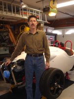
KV-BlackjackZeroKit4.jpg
 
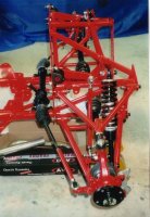
I rode over to Kurt's house last Saturday to look at his project and all I have to say was IMPRESSIVE ! Kurt had the frame and suspension pieces powder-coated red. The Guzzi motor, VW trans and suspension and brakes are all bolted up. He`s doing a fantastic job on a very cool kit. Very good quality stuff and one of a kind here in the US!
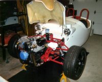
Cant wait to see it again when it`s even further along. Cheers, Bill R.
 
Hey, no time, but here's a picture of the real deal. Kurt
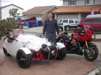
 
Welcome Kurt! I had to relink the pictures above, they should be there now. I'm looking forward to your next article.

Guys Gonzo is the builder of above if you haven't made that link.

Ren
 
Part 5

Last month I wrote mostly about fuel injection issues. This month I want to continue with other electrical widgets. I could save a lot of money by using spare parts from various vehicles that I have, but that’s tacky. I often did that in high school when economics necessitated it. I even remember brush painting one car I had. Now that was, well, memorable, to say the least. But now those days are behind me and I can actually purchase the right parts for the job. I’ve learned that there is a whole other world outside the junk yard.

I decided to use Stewart Warner DLX electrical gauges along with their corresponding sensors and senders. The tachometer can be calibrated to operate from 0.5 pulses per crankshaft revolution, PPR, and up. This is important because 0.5 PPR is the signal produced by one Guzzi ignition coil and not all tachometers can operate at so low a PPR. I decided to use the revolution counter output from the ECU which is 2 PPR because it will produce a cleaner signal than the ignition coil. I will also use this same output to operate the WEGO III oxygen monitor. It also must be calibrated and has an operating range of 0.5 to 12 PPR. The WEGO III will also be connected to the throttle position sensor, TPS, input on the ECU. With this configuration it can display and remember an air / fuel ratio, AFR, table which matches the format of the Power Commander table. This takes a lot of guess work out of making manual changes to the Power Commander.

The speedometer must be electrical because there is no mechanical output from the VW transmission. I made a 16 tooth tone ring that mounts on the transaxle (FWD) with a permanent magnet sensor pick up that will produce the pulses needed to drive the speedometer. The speedometer will need calibrated once the car is running.

I bought a power distribution panel which contains 16 mini fuses and 2 relays from Ron Frances. The model JP-10 isn’t cheap, but sure is nice. Its greatest attribute is packing a lot of wiring into a small box. For more information see www.ronfrances.com. It didn’t come with a schematic so the first thing I had to do was test all the connections with a meter and make a schematic. I made two internal wiring changes and relabeled all the connections and fuses to suit my needs. It’s very well made. I would recommend it to anyone. I also bought 6 more relays and bases from Ron. Total, I have 8 relays and 15 fuses in my electrical system.

Being a Guzzi lover, I wanted to use as many Guzzi parts on the motor as possible. I needed a voltage regulator and, even though I was armed with the parts book, received the wrong one from the dealer. After a phone call and a description of the old wiring harness I received the correct one. It seems that the parts manual is wrong. Gee, I never had that happen before. I could have bought a different regulator for one third the price, but it just wouldn’t be Guzzi. ' Got to support the dealers. I’ve seen and read some wacky things on the internet that people have done to their bikes just to save a buck. I just shake my head and wonder, “why didn’t they just use the part from Guzzi?” It’s one thing if the Guzzi part isn’t any good, but 99.9% of the time they’re just fine. I only know a hand full of people that are capable of designing and building parts that are better than OEM.

I’ll be making a metal dash so changes in the design after construction wouldn’t be easy. Ninety percent of the vehicle’s electronics will be packed behind the dash. All components have to be laid out in advance, even switches for future use. With this in mind I want a stereo that wouldn’t be outdated next year. It also has to withstand the demands of a convertible in So. Cal. I decided on a Sony marine stereo. It’s UV, water and salt resistant and has more gizmos than anything I’ll outgrow. I also purchased a pair of marine speakers, but have yet to figure out how to make them fit. I won’t be setting any records on cup-holders ether.

While studying the Stone’s electrical schematic I found several errors made by Guzzi. Only one was huge. This is much better than my SP II was. That schematic was so bad that it was useless. The factory has gotten a lot better, but they still aren’t up to my standard. I needed to use a pattern for making the Blackjack Zero schematic. My experience tells me that nothing beats aircraft schematics, but I don’t have one on hand to copy its format. The next best format that I know and have is Ford cars. So, I used it for my pattern. I put a lot of time and thought into it because it will be the only fuel injected Guzzi Blackjack Zero in existence. Sooner or later, someone will need to make another one. So what started out long hand is slowly being transformed into a typed manual.

One little oddity that I purposely created is wire color and number usage. Since I work on elevators I have a lifetime supply of wire. Therefore, I’m using elevator wire wherever possible. Elevator wire is pre numbered every foot and the colors change every ten numbers. It’s a great system unless you’re color blind.

Until next time, keep the smoke in the wires.
Kurt
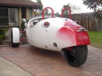
 
Now, the complete Guzzi kit is 9400 sterling + engine. It's not exactly cheap.

I think I would be capable of building one, with time and patience (same with a Caterham or similar) but it would take me ages to enjoy it.
 
Oh Man!

What a project! Congrats on yer stick-to-it'ness.

Do you find yerself expanding the work area and forgetting where ya put things?

Watching your steady (?) progress makes me wanna do a favorite pipedream project of mine. http://www.velocityaircraft.com/

Keep up the good work. And more pics please...

Alex
 
Part 6

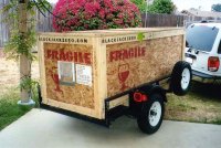
Well, the big day finally arrived. After months of looking at pictures, planning, building and scheming, the crate containing the Blackjack Zero kit car from Great Brittan arrived at the Port of Los Angeles. From the time of order to receipt of the car was seven months. Some minor delays were due to the shipping company.

Upon ship’s arrival, I was informed by a logistics company of obligated fees, paperwork and did I say, fees. I have never done this sort of thing before so I asked a lot of questions. I guessed two to three hundred for a customs fee. I was actually pretty close. What I wasn't prepared for were the myriad of other sometimes baffling fees tacked on by seemingly everyone who could gain from touching the paperwork, crate or it physically being within their legal jurisdiction. So triple the customs fee and that's what it costs to get a crate through the Port of Los Angeles. Ouch! Putting the unpleasantries of the dent in my VISA aside, the actual pick up went very smooth. I drove to the warehouse with my trailer, it was loaded and I left. It took one and a half weeks to process the crate through customs.

KV Arrival2


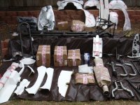
When I returned to San Diego, my wife remarked that I looked like a kid at Christmas while unloading and unpacking the crate. She called it a giant toy box. Gee, I don't know why? I enlisted the service of my son to help unpack my Christmas present for the next 20 years, or whatever I told my wife. I first checked for any shipping damage. With the exception of one heavy piece that came lose and scratched a fiberglass part, all looked very good. I next arranged the parts in the yard for a picture then repacked what I didn't immediately need while the rest went to the garage. While sorting everything out I found the inventory accounting for every nut and bolt. That's nice, but what I was really looking for was a CD containing the assembly instructions. After an e-mail to the manufacture I found out that none exists. Oh, that's nice. This is going to slow me down a little. I'm up to the challenge! I guess it's my fault for presuming that I would get one because a 14 page assembly instruction exists on the manufactures web sit on a pdf file. I thought this was a sample, but learned that this is everything. I don’t know what a novice would do with only 14 pages of instructions to build a car?

KV Arrival4


Where to start without any instructions, I thought for a moment? I decided to check all the parts that I made or bought for proper fit. Prior to the arrival of the kit I knew there would be some close fitting parts. First I temporarily fitted the transmission in the frame. I had a high torque starter, which is larger than the standard starter that the manufacture uses. No problem, I had a quarter inch to spare in the frame.

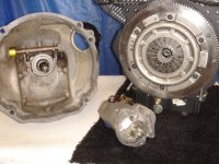
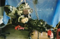
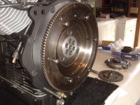
I next retrieved the pieces for the adapter plate, flywheel and hub that mate the Guzzi motor to the VW transmission. I found that my lower bracket that connects both throttle bodies to each other overlaps the adapter plate. Two hours later armed with a new and improved bracket I overcame that hurdle.


KV VWClutch8

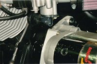
The motor I used, 2003 Stone, has the throttle potentiometer mounted on the bottom of the left throttle body. Due to clearance issues with the adapter plate I had to reposition it 180° from the forward pointing stock position. With the plug pointing rearward it now just touches the top of the transmission where the bulge is located that the starter fits in. The electrical connector fit fine, but I filed a little aluminum off the transmission anyway. I don’t want any wear issues from vibration.

KV GuzziTPS

I next found out that I had to grind off a half inch from two air fins on the lower rear part of the motor. This enables an allen wrench to access the new bolts that connect from the adapter plate to the transmission.

Ok, next it's the clutch and pressure plate. That wasn't happening at all. I had a 200mm set up that is correct for the 1971 VW Beetle transmission that I have, but the custom Guzzi flywheel is 180mm. After another e mail to you know who, I found out that the correct clutch and pressure plate is 180mm from a 1953-1966 VW Beetle. Back to NAPA for a return and reorder and I'm back in business.

I had previously installed an oil temp sensor and fitting for the oil return hose (crank case vent system) in the rear of the oil pan. These two parts are directly forward of the front transmission mount bracket. I wasn't about to move the engine parts, besides, they’re located in the most logical place. I decided to drill holes in the transmission mount bracket which removed 90% of the bracket and weld steel plates above and below the holes. Well, if it all bolted together like an erector set, where would the challenge be?

The kit comes with an aluminum sump oil baffle for the motor that looked real well made so I installed it along with a new dip stick that I made. While I was on the motor I started replacing electrical connectors with weatherpac electrical connectors.

KV EngTransAssy1

I then put that aside to prep all the steel parts for powder coating. All the pieces were bare metal and had a little rust in a few places. The rust was irrelevant because everything would get sand blasted anyway. All the welds looked professional, but I did smooth a few out where they would be more visible and removed the weld BBs.

The car does not come with a front bumper. The motor is the bumper. This really concerns me and everyone else I’ve talked to. I knew that a bumper would have to be designed and made, but haven’t had time to do it. After close examination of the frame I decided to drill and tap a few strategically placed holes for mounting a future bumper. I also drilled some holes for mounting electrical components.

Well, that’s enough for this episode. Tune in next time for the assembly of the frame and installation of the motor.


Kurt Vogt


Part 7

Small bits and pieces become larger assemblies. In this part I want to talk about assembling the frame and power train. As I look back at this evolution I think of three things: good design, trips to the hardware store and more parts made or modified on the lathe.

There were many small setbacks as I put pieces together, but overall, it was clear to me that the manufacture put a lot of thought into the design of this kit. As one who has always been maintaining, designing and building widgets, I know good and bad designs. If it's bad, you will hear me complain about the college educated engineer who obviously never had to build or maintain the junk they designed. Believe me, there is a lot of it out there. I suspect the designer, Richard Oaks, did a lot of assembling and disassembling in the process of designing because everything is quite easy to be maintained after assembly. I have the 10th copy of the Black Jack Zero and I can see where design improvements have been made from its predecessors. I must say that the design concept is superb in form and function. After assembling the frame and drive train it is very satisfying to see all the pieces work together in unison. For any mechanic, it's pure poetry. My wife wouldn't understand this at all. But to those of you who might be contemplating a project of this nature you will not be disappointed with the Blackjack Zero. As stated in a previous article, I'm not a VW person, so I can't vouch for the VW motored version.

I must say that one of the most challenging aspects for me has been assembling with little to no instructions. Some things are obvious and others require close scrutiny of pictures and a measuring tape to figure out. A few questions required an e mail to the manufacture to gain understanding. Richard Oaks always promptly replied to my e mails which have been a great help. In my opinion, if this kit car is to be assembled by a layman there must be more than 14 pages of instructions. So far, in my experience with this kit, this is the weakest area that needs improvement.

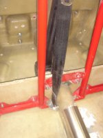
I started frame assembly with the 5 rotating arms. These are the upper and lower left and right "A" arms and the rear swing arm. All require bushings of various design and coming from different donor vehicles supplied with the kit. The lower “A” arm bushings are made of solid rubber and do not require lubricating. The upper “A” arm bushings are made of eurothane and in my opinion should be lubricated. So I added grease nipples. The rear swing arm bushings are made of nylon and require lubricating. The kit came with a package of grease nipples, but no holes in the swing arm. So I drilled and tapped to fit. Upon assembling the bushing in the arm I noticed that it was way too tight. So I disassembled, took off a few thousandths off the sleeve OD and reassembled. All the arms required shimming. I found that the best way to make the shims was by using stainless steel washers cut to the right thickness on a lathe.

I next turned to the ball joints. The uppers went smooth, but one box of the lowers was missing its package of hardware. I wanted the left and right to look the same so I bought replacement hardware for both.

I then pressed the front wheel bearings into the wheel uprights or steering knuckles as it’s called by another manufacture. I installed this assembly onto the ball joints. Then the drive axles and hubs were installed. There is only one lock nut that retains the wheel hub to the axle so I drilled and added a cotter pin for added safety. Hub dust caps did not come with the kit so I purchased and installed a pair. The rest of the linkage, steering and stabilizer bar, went pretty smooth. I made steering stops to prevent the steering linkage from hitting the frame. I made all the linkage adjustments with the suspension in full drop. I’ll readjust it latter when the car is complete and I have weight on the wheels.

The rear spindle mounted nicely on the swing arm. After pressing the bearing races in the hub, I noticed the spindle nut was missing. It became a small setback because my hardware store didn’t have it. After a few calls to automotive stores I located this unusual extra fine metric nut. The rear hub came with a dust cap.

The springs and shocks require assembly. A spring compressor tool is really needed to assemble them, but since I didn't have one and didn't want to buy one I had to find another way. I compressed the springs in my press, installed four temporary wires around the circumference to retain the compressed state. I could then slide the springs over the shocks, install the retainer and release the wires. Be sure to install the correct spring to shock. The rear spring is different.

In my opinion, all three brake rotors are much heavier than necessary for a thousand pound car. I had a machinist neighbor, lucky me, drill cooling holes in them to reduce weight, improve performance and for visual appeal.

The brake calipers are very nice quality. The fronts have four pistons and rear is a single piston with an emergency brake mechanism. I only had three issues installing them. I had to remove .020˝ from each pad to allow suitable clearance for the thick rotors. The calipers didn’t come with anti-rattle clips to keep the pads from rattling. So I made my own. The mounting spacers on the front calipers were the wrong dimension. So I had to make those too.

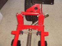
In preparation for mounting the motor/transmission assembly into the frame I put about 100 pounds of weight on the rear of the frame. The engine projects in front of the frame which is on jack stands. There’s a lot of weight up front and nearly nothing behind it at this point. Three bolts and you’re done. It took maybe 15 minutes with my son and a chain fall. I like it! I later experimented with the weight distribution issue and discovered that I really didn’t need to add temporary weight on the rear of the frame. If the motor was about 50 pounds heavier I would though. That’s pretty close so I think it’s prudent to add weight. Connecting the drive shafts is easy. That’s another 30 minutes. I decided to install the tone wheel I made for the speedometer to the left driveshaft coupling. It will work on ether side, but the left is more hidden by the starter.

If you look at Guzzi Blackjack Zero carburetor and fuel injection pictures there is clearly one benefit, density. My fuel injection set-up takes about half the space of the manufacture's single carburetor set-up. This frees up a lot of room rear of the air filters for mounting whatever you want. In my case it will be the crankcase vent canister and breather. I had to modify the K&N air filters that I installed for clearance to an adjacent frame cross member.

I then mounted the tires with the lug bolts to ensure proper fit and take a few pictures. They more than fit. The brake pads can be changed without removing the tires.

If you are contemplating a project like this, here are a few things to consider. Through this process, there were many trips to the industrial hardware store. I have one of the best just 3 miles away. I can’t imagine trying to do his via long distance or by ordering. Also, I wouldn’t take on a project like this without access to a lathe. You can get by without a mill, but not a lathe.

I think I’ll take a break, give my wife some well deserved attention then start on the exhaust. Sounds like a plan.

Kurt Vogt

KVFrame4F KV VWClutch5 KV Parts1
 
Part 8

My giant toy box of parts is getting empty. I can see the bottom now. The lump in the garage is starting to look like a car. My daughter says it's the weirdest car she has ever seen. Beauty is in the eyes of the beholder.

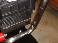
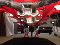
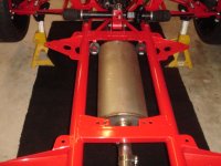
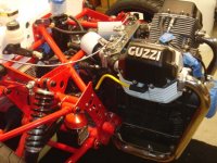
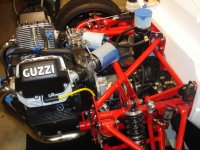
I next turned my attention to the exhaust. Just like the brakes, it’s way oversized for our small Guzzi motors’ needs. Over built is better than under built I say. I figured out where the exhaust weld nuts needed to be placed for the WEGO III. I placed one in the left, right and common exhaust pipes. The left and right are nearest the lower front corner of the motor and the common one is just upstream of the muffler. The WEGO III oxygen monitor can only support one sensor at a time. Ideally, I would want to monitor the left and right exhaust oxygen levels at the same time, but that's too expensive. So I plan to use the common location most of the time with an option to move the sensor to the left or right exhaust in the future. I cut the holes in the exhaust pipes and delivered them to a friend of mine. He's way better at welding than I. I'm certified for heavy steel stuff used in the elevator trade. I don't do dainty things. Bob Ross recommended that I polish the stainless steal exhaust so I did. It looks great, but I don't think it will last long. I assembled the complete exhaust system on the car then removed the rear half. It all fit and looks great and so it's off to installing the main fiberglass body.


Prior to installing the main body, holes need to be cut for the rack and pinion shaft and rear of the transmission. I cut the holes according to the instructions provided, no fit. The body was designed to be installed prior to the motor / transmission installation. Not wanting to remove the motor / transmission assembly I modified the size of the hole for the transmission. After three attempts, and some help from my son, it was a go. During this process I temporarily assembled the steering column linkage to set and lock down the rack and pinion angle. I wanted to final the rack and pinion prior to the installation of the body because the mount bolts are a little hard to reach once the body is on.


After the body was positioned on the frame, I accurately drilled and installed a few of the main mount bolts. From that alignment countless other holes connecting the body to frame were drilled. Next is where things get a little slow. The next step is to drill numerous other holes in the body to mount all sorts of widgets. There are dimples molded into the fiberglass where holes should be drilled and scant information as to their purpose. Prior to drilling I had to verify the purpose of the hole and the accuracy of its location. The accuracy is no problem, but the purpose is. Since there are no instructions saying, mount this there. I had to figure out what goes where, back to the pictures. For example, there are holes for mounting a VW oil filter on the fire wall. I certainly don't need that. I have twice the wiring than the original kit has. That's twice the holes there. I don't have a choke with fuel injection. I skip that hole and so on. There are probably 50 issues like this. With all this hole stuff, I've only managed to make one mistake so far.

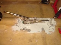
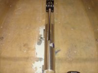
Oh, here's one issue that stopped me. My kit, #10, was the first to have a new hand brake lever. The lever is great, but it can't be mounted it in the same manner as the older version. I could figure it out on my own, but it would be a long process. I would have to temporarily install the seats, with upholstery, and the gear shifter mechanism to locate the best possible location for the hand brake lever. Before I can install the seats I would have to install the roll cage. Oops, I still can't install the seats until I receive the seat adjustment tracks that I ordered from England. This is too much of a delay. I just e-mailed the manufacture and he sent me a picture via e-mail. In his picture, the hand brake lever is mounted on the left side of the tunnel. This is quite easy, but too close to the right side of the left (passenger) seat. What I really wanted was to position it in the center of the tunnel with the mechanism inside the car. This is probably the most difficult solution, but doable. The fiberglass tunnel is empty since the car is FWD and the exhaust runs under, not in the tunnel. It’s only real purpose is structural. So after 8 hours of work I had a chunk of the tunnel off set, brake lever mounted in the center, cable relocated and a panel made to fit over the off set. The purpose of the panel is to keep dirt out of the mechanism and form a continuous tunnel shape for the carpet. Now if I could just squeeze in a cup holder or two.


Another challenge, it wouldn't be any fun without these little brain teasers, is to figure out what hardware goes where. This isn’t much different than a jig saw puzzle. I open up a bag, separate the like items into piles, count, scratch my head, count again, and then determine there isn't enough or I don't like my choices. I make a list for this week’s run to the hardware store. The hardware provided is all stainless steal and my purchases have been almost all stainless steel also. I'm up to $175 of that stuff so far. I must admit that I am picky. For example, the bases for the quick release fasteners (DZUS) that secure the movable panels are held in place with small wood screws. I replaced them with 4mm countersink bolts, in stainless steel of course.

About this time, Bill Ross e-mailed me to see if I wanted to share the cost of a Guzzi motor for sale on E Bay from Mark Etheridge at Moto Guzzi Classics. It had the hydraulic valve recall installed that I needed and the cylinders, heads and block that he needed. I said, sure, he won the bid and we were happier than two pigs in a mud hole. Life doesn’t get any better than that. I plan on installing the recall parts after the car is running unless I run out of money and have time on my hands.

The gas tank is a beautiful work of art in aluminum. I didn’t want to see it corrode so I had it powder coated. I installed it along with a Stewart Warner fuel level gage. The fuel level gage mount flange inner and outer DIA are almost identical to the existing hole for the gage. I got lucky there. I knew ahead of time that I would have to drill and tap new holes to screw it down though. That’s a piece of cake. I also installed the Aston fuel cap. It’s pretty slick lookin.

The manufacture sent me a modified bracket for the rear shock. It changes the range of swing arm motion. I installed it knowing that some body parts will have to be trimmed to fit due to this change.

Well, that’s enough fun for this month. I hope you’re having some too. It’s time to get out those winter cloths and keep riding.

Kurt

KVEx2 KVEx3 KVEx4 KVEx5 KVEngBay1 KVEngBay2 KVEngBay3 KVEngBay4 KVEBrake1 KVEBrake10
 
Part 9

Well, I'm still working on the main body. It may seem a little slow on the surface, but actually, I'm getting a lot done.

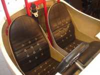
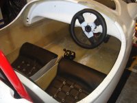
I purchased a set of 3 point retractable seat belts from Retro Belt USA. They’re very nice quality. Of course I had to shorten them because this car is so small. Blackjack Zero’s system for securing the seat belts is a little different. One interesting thing is that the location of the reel and buckle are reversed outboard to inboard. It still works just fine though. I made brackets to take a half twist out of one end of the lap belt and added a bracket on the seat bucket. I also moved the retraction reel down a few inches in the storage area to conceal it better.


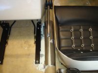
The seat buckets tilt forward allowing access to the cargo area behind the seats. That's nice, but they aren't adjustable. So I purchased two pair of seat runners from TILLETT in England. They aren't cheap, but work perfect. There aren't many choices due to space limitations. The seats slide forward enough to access the cargo area, but I decided to keep the tilt function anyway. It’s a little more convenient. I was able to use the manufacture’s brackets, but had to flip them upside down and re-drill a few of the holes.


The bracket I made for the bucket is a clip to hold the short nonadjustable part of the seat belt from falling to the floor when disconnected. Although the space between the bucket and wall is big enough to fit your hand down, I prefer not to play fish each time I need the buckle. It can be easily unclipped when the seat is tilted forward.

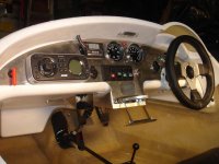
I also completed the dash. Wow, where to begin? There was a lot of planning even before the kit arrived. The number one issue is space. There is only so much real estate. The number two concern is power consumption. Our little Guzzi alternators produce quite a few less gigawatts than a normal car. In the end, I decided on: five electronic gages, four indicators, eight switches and six devices on the dash. There are a couple of other electrical switches and devices located elsewhere.


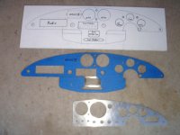
The kit came with an aluminum dash designed for the manufacture’s electrical system. It covers a little more than half of the fiberglass dash surface behind it. It was quite useful in making the outline for my full span dash. (See picture) After that I set it aside. Next was a game of puzzle again. I made two dimensional patterns from my three dimensional gizmos. I covered my plate of aluminum with tape, traced the outline, and then tried to fit everything inside the lines. I cheated a little by adding a small center console. As you can see in the picture the stereo takes up a lot of real estate. The full span of the dash can be reached from ether seat. Considerations were made for the steering wheel obstructing my view, ergonomics, which controls are used more frequently and which gages and indicators are more important to see.

I wanted to have a turn signal lever much like a normal car. I couldn’t find anything close so I had to make it from scratch. I have a short lever just to the right of the steering wheel, RHD, which passes through a bushing mounted on the dash. Inside the bushing are detents and a slot that limits the range of motion. The transmitting shaft is connected to an arm which actuates a toggle switch. It’s not self canceling, but sure looks clean on the surface.

I wanted to mount the horn on the steering wheel. Since the steering wheel shaft has a ¾” DIA hole it’s doable. I made a switch that fits inside the shaft, brought the wires out through two holes and connected them to home made slip rings. Two pick up arms ride on each slip ring to provide the continuity needed for the circuit. What are a few more hours of work to get it right? Don’t try this without a lathe.

Do you remember that small center console I mentioned? Its primary purpose is for a cup holder. Yes, I finally managed to fit one in! I was searching for other parts on the web when I ran across an AutoLoc billet aluminum cup holder on Summit Racing’s web site. It’s the neatest thing that folds into a slot revealing only a 1˝x 6˝ face. I just had to have it and make it fit.

Just above the cup holder is a small aluminum electronics project box. It’s kind of like a very small glove box without a door. Its purpose is to provide a means of storing and pulling out the IPOD connector and cord. It also provides a place for storing the IPOD or cell phone. I had to cut out a good chunk of fiberglass to make it fit. After the installation was complete, I fiberglassed around it making it part of the body, not the dash.

I had to mount the WEGO III on the surface of the dash, but wasn’t happy that the wires are attached to the front of the display. Not wanting to cut a hole in the aluminum dash to stuff the wires through, I did the next best thing. I cut a hole above the dash, so much for the clean look.

Lastly, I needed a way to access the connectors for the Power Commander, WEGO III and engine diagnostic from the passenger’s seating position. I decided that a swing panel under the dash was the best way to do it.


All this work leaves me little time to ride. So the last couple of years, I’ve squeezed in most of my riding on the way to church Sunday morning via 200 mile excursions. Usually, twice a month, year round, I leave home about 5:15 AM on my V11 Rosso for East County. In San Diego that’s a synonym for the desert. I actually prefer greener landscape, but that isn’t happening in So. Cal. Depending on the time of year, it can still be dark for quite some time. I live near the ocean so it takes me about an hour to get to real nothingness. Once in Wile E. Coyote and Road Runner country speed is whatever you want. Other vehicles are almost nonexistent and wildlife is still out foraging. Once in East County I can choose mountain twistys or flat straights that beg for triple digit speeds. I can see how much rubber I can wear off the sides of my tires or go looking for deer, turkeys or other wildlife. Sometimes they find me first. I’ve had a few of close calls. I sometimes stop to listen to the absence of man or watch the sun rise on the desert floor from mountain tops. That’s a sight to behold. Ten minutes of sun rise is worth the 200 mile trip alone. Too bad I’m not a photographer. I always have a great time, unless there's bad weather. The wind can change from a gentle breeze to 50mph wind gusts in 20 minutes. Sometimes there's snow in the mountains when it’s 60°F at home. I have to remind myself not to forget my winter gloves. As I head back to civilization, the city dwellers are just starting to come up the mountain with their RVs and desert toys. It's a great way to start the day and put life back into my bones.

Kurt

KVSeatBelt2 KVSeat1 KVSeat2 KVSeat3 KVDash1 KVDash4
 
Part 10

The car keeps slowly growing like the tales from pit road. I don’t know a darn thing about racing, but I do know that my loving spousal unit sure will be happy when it’s done. I still haven’t been able to enlighten her that there is a certain pleasure in turning a discarded piece of scrap metal into a functional auto part. On the other hand, I don’t understand why anyone would want to learn Japanese tea ceremony where one spends a lifetime learning how to make and serve tea. I guess that is why Men are from Mars and Women are from Venus, one of my favorite books.

I'm still working on dash related items. I didn't realize just how much is associated with the dash. I thought I would finish this area before moving on to another.

I grew up owning and fixing mostly 60s era cars and motorcycles. I remember really liking those hi beam stomp switches on the floor of cars back then. Does anyone know why they are gone now? I decided that I just had to have one for my car. The switches are still easy to find so I picked one up. That's where the easy part ended. There's painfully little space to squeeze that switch on the side of the tunnel as far away from the clutch pedal as possible. Of course this necessitated reshaping the fiberglass tunnel to fit and mount the switch. I now have about 1/8" space between the switch and transmission with a thin fiberglass wall between.

I squeezed in a small light fixture above the center of the dash inside what the manufacture calls capping. I call it cockpit molding. It provides about a 5˝ overhang above the dash. Anyway, after another shoe horn fit, I now have a nice flush mounted map light.

I mounted a micro switch in the cavity that the emergency hand brake is mounted to actuate the emergency brake light on the dash.

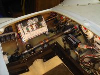
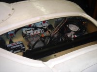
I next turned my attention to the behind the dash widgets. I have a lot more electronics than the manufactures version. He made nice fiberglass panels to separate the electronics from the storage area. In the end, I was only able to use part of the panel that covers the battery. His panels screw in which does not allow easy access to the electronics. I decided on a 1˝ by 3˝ tall aluminum angle screwed to the floor with Velcro attached to the top edge. There will be matching Velcro attached to the underside of the top and fabric between. This will make accessing the fuses, relays, power commander, etc. much easier. I wanted my storage area to be as large as possible without mounting the widgets so close together that they couldn’t be easily serviced. There is some wasted space. It's an odd shaped cavity anyway. Many of the components could be mounted in the engine cavity, but, unless it needs cooling, I wanted to keep them out of the weather. I crafted some of the weirdest compound angle brackets to mount the ECU, fuse box, relays and power commander around the steering column area. A screen covered circular hole was made directly under the ECU for cooling. A fiberglass cover was installed over the turn signal slip rings and pick up arms to prevent them from causing any problems. I thought I was done in this area until I started on my next project.


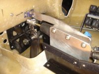
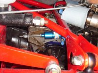
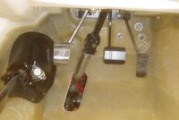
The manufacture uses a cable to actuate the clutch. That would be OK, except in order to connect A to B the cable has to make a 360° bend; not good. Initially, I thought I would make some kind of lever system to connect A to B, but then I thought; hydraulic is the way to go. E bay to the rescue! I purchased a hydraulic clutch kit made for VW Bugs and Ghias. After chucking the kit's brackets and removing the car's transmission cable bracket, I was ready for what turned out to be more difficult than I anticipated. The stainless steel bracket I made for the slave cylinder on the transmission was a real work of art. Next to mount the master cylinder, oops, where? I spent two evenings measuring, staring, positioning, and making rough templates. They all sucked. There just wasn't any way to get a direct line of access from the pedal arm to push the cylinder’s plunger. The frame, sway bar or transmission hydraulic cylinder were in the way. I couldn't make it fit without creating a friction generating mechanism to turn a corner. I really wanted to mount it in the engine compartment, but it was looking real ugly. So I started looking on the other side of the fire wall in the storage compartment. I could mount it above the pedal fulcrum with some modification to the pedal arm, but then it would be in my storage area. I already built a nice wall. Everything was looking nice and tidy. What I ended up doing was modify the pedal box to move the clutch pedal from the left to the center of the box and make a new clutch pedal. The new pedal arm angles over so that the pedal foot pad is in the same position as the old one. This creates a little more friction, but now I can mount my cylinder in line with the pedal arm just over the steering shaft and out of my storage area. There's still plenty of room to access the electronics behind it.


Since I, once again, think that I am done in the storage compartment. I installed the hatch cover and hardware. The panel needed trimmed as expected. What I didn't like is how position sensitive the 90° quick release fasteners are. I needed to add several rubber bumpers to achieve a flush fit when closed and shim the stationary hook fasteners to their proper height. The locking part must be in near perfect alignment over the hook for smooth operation. Later I will need to add a seal to the circumference of the opening. The manufacture designed a nice molded area for a seal and channel to drain the rain water. During this process I made the tool to open and close these fasteners. They have a wide radius slot similar to a countersink regular screw. I'm very familiar with this type of fastener because of my experience working on F4 Phantoms in the Marines during the '80s. We called the tool "snoopy", I suppose because the shape had ears like snoopy.

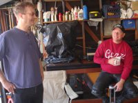
I had scheduled an open garage day for anyone who wanted to see a partially built Blackjack Zero car. I figured I had enough assembled by this time to make it interesting. I sent out a few e mails, placed a post here on the GuzziTech Southwest Region forum and left it at that. This turned out to be a good opportunity to take a break, clean up the garage, take a few pictures and catch up with some of my friends that I don't see enough. It's tough to get people together with all our weird busy schedules. For those who couldn't make it just give me a call and stop by. I'm usually working on something in the garage. Good camaraderie was had by all which matched the nice sunny day in San Diego.


I now set my sights on the engine compartment. There's ample space to mount all the components, but function isn't my only criteria when making assembly decisions. I see art in well designed items from mixers to motorcycles. Maybe I'm partial, but I think Italians are really good at their ability to meld with the forces of nature. The result of their design philosophy gives one a new appreciation for being alive. Driving or riding becomes more than a mechanical task. The relationship of all of the elements that are required to make a machine functional is not nearly enough to satisfy the builders and engineers of Italian car and motorcycle makers who have built their reputations on exceeding a customer’s expectations. It is the love of beauty that is the central focus throughout the history of this industry in Italy. For anyone who has driven an Italian car or motorcycle it would be difficult to call the experience boring.

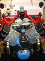
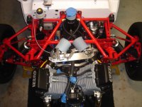
I mounted the crank case vent tank and breather centered above the transmission. Each ignition coil and horn is mounted just behind the frame beside each cylinder head. The speedometer pickup sensor is tucked in next to the tone ring on the left transaxle. The fuel pump, regulator and filter are mounted on the left side of the firewall. The voltage regulator is located under the brake master cylinder. This pretty much takes care of the engine bay except all the electrical spaghetti. I think I’ll start on the hood tomorrow.

Kurt

KVDashB1 KVDashB3 KVHydClutch1 KVHydClutch4 KVPedals2 KVOpenHouse111409 KurtVogt KV BlackJack Progress210
 
Terrific project and exaction but it makes me want to go and burn down my shop as I'm very much an amateur by comparison. Really liked your comments about Italian designed items, even with some of their minor faults we are very much attracted to them. They are not boring. Lastly, thank you for doing this and writting up your project build, keep it coming!
 
Kurt says "I'm now ready to disassemble everything for painting."

KurtV BJ Prog210 KurtV BJ Prog210 2
 
The Making of a Moto Guzzi Car

Part 11

The holiday season brought lots of good company and merriment my way which resulted in the car project seeing less action than normal.

I installed compartment lighting in the left and right rear storage areas behind the seats and the front storage compartment. I also solved a problem that had been bothering me. Previously, I had said that I was only able to use part of the panel that covers the battery in the storage area. This same panel also serves as part of the flooring in the storage area. The panel fit and functioned well, but there was no way to gain access to the battery without removing 6 bolts. I feel that no tools should be required to perform battery maintenance. The solution to the problem was cutting the battery panel and inserting two piano hinges and one quick release pin. It now folds up completely out of the way by pulling one pin.

Next, I installed the hood. I knew it was going to be time consuming, and it was. The hood is composed of two fiberglass pieces. There’s a common main hood and a, depending on which kit was ordered, panel that ether ‘fits’, I use that term loosely, a Guzzi or VW motor. The two were easy to trim and bolt together. I then trimmed and installed the left and right fiberglass fairings on the frame that are used to secure the front of the hood. The left and right front of the hood is secured by button head bolts. Four 90° quick release fasteners secure the sides along the rear edge. After some rough trimming I decided that I needed to locate and install the two front fasteners. There are molded lines or dimples in the fiberglass where all components need to be cut or drilled. I’ve learned not to rely on their position. They’re sometimes off, but are helpful in providing a reference point. According to pictures of a completed car, flintstone building, there should be metal plates attached to the hood under the screw heads. There weren’t any in the kit so I made my own that sandwich the fiberglass, preventing the hood from chaffing.

Before I could determine the proper position and install the nut plates for the front hood bolts, it was first necessary to do a lot more trimming around the motor and throttle linkage. Even though my throttle linkage is very compact and I couldn’t have made it any smaller, there was still interference with the hood. I don’t blame poor designing. Remember that the kit is designed for a single carburetor. I am the first guinea pig to use fuel injection. Anyway, no worries, a ¼˝ of clearance could be obtained without much difficulty. Some Guzzi motors have the throttle linkage on the bottom of the throttle bodies. That would solve the hood clearance issue, but create an irreconcilable clearance problem with the VW transmission and adapter plate. I knew none of this when I selected my donor motor. Luck was on my side this time.

Anyway, back to the fitting, with the front of the hood now secured and the hood rough trimmed I attached the hinges. I know it sounds backwards, but I start with the most critical areas first. Now that the hood is going to stay on the car and be in my way, I needed a means of holding it open. Flintstone building reveled that only the friction in the hinge holds the hood open. That will work until the first gust of wind or the hinge loosens. So I built a simple rod arm support from scrap materials lying around and a fiberglass receptacle on the hood.

I next turned my attention to the 4 quick release fasteners. The anchor plates for these fasteners must be positioned in a molded recess. The moveable fastener must be aligned to the anchor plate beneath it. To obtain correct alignment I made a steel centering pin with a protruding tit that fits into the anchor plate. It’s the same idea as a dowel center used in woodworking. A dent is created on the inside of the panel by tapping the outside while over the anchor plate containing the centering pin. I then drill a pilot hole from the inside out and final holes from the outside in. When drilling the final holes there is a tendency for the drill bit to wander around so I make marks on the outside of the panel prior to enlarging the holes. Since there are only a total of 13 of these fasteners, it’s not worth my time to make a jig.

With the hood completed I now turned my attention to the head lights. I had to obtain my own since I didn’t buy the electrical kit for the car. The diameter, 5 ¾˝, wasn’t a problem. The problem I had was finding a car mount and adjustment for that size. It turns out that it’s a common size for current motorcycles and antique cars. I found a kit car company in England that sells them as an assembly that includes the mount, adjusting hardware and light for both left and right hand drives. When they arrived, the first thing I did was fit them by hand; you guessed it, another shoe horn fit. The assembly is fixed to the main body while the hood fits around it as it's lowered. Therein lies the problem. If the alignment of the mounting hardware and light isn’t spot on, it ain’t happening. Even with correct alignment the two gently rub each other when the hood is at an intermediate position.

The kit car came with two concave fiberglass pieces that need molded into the body. These provide the space needed for the protruding light(s) electrical connectors. The light kits that I bought also came with similar pieces, but in plastic. I decided to use the fiberglass ones. The adjusting hardware that came with the lights wasn’t going to fit so I made my own. In the end, I only used the lights and bezel rings and even the rings had to be modified. The mount assembly is pretty straight forward and simple. What took a long time is obtaining proper alignment. One interesting thing I learned from looking at pictures during this process was that the manufacture’s headlights appear to be smaller in diameter than mine. After further investigation I found that the lights used by the manufacture are the same diameter as mine, it’s just that the hole in the hood that reveals the lens of the light is about 1˝ smaller in diameter. I had cut a hole in my hood the full diameter of the light minus the bezel ring. In retrospect, this produced better lighting, but was harder to fit.

I next retrieved the fiberglass fenders from the toy box. I had to make two modifications to the front fenders. The steering stops that I made permit a few more degrees of turning than the kit’s stops. This necessitated some extra trimming to prevent fender interference with the upper A arms and steering tie rods. The front fenders are rather thin and flex quite a bit. I was apprehensive about possible stress cracking and contact with the tires during flex since they fit so close. I added a 2˝ wide strip of fiberglass reinforcement around the inside of the front and rear portion of the fenders. I also molded in fender washers at the mount holes. This made them stiff enough to satisfy me. The rear fender needed none of this and bolted right in, in 30 minutes.

The next items installed were the rocker panels. Two people are required to install the rocker panels, one inside and one under the car. I had previously fit, drilled the bolt holes and removed them. All I had to do was trim, finish and reinstall. That was all straight forward except for one change. Since the first fitting, the manufacture sent me a modified replacement upper mount for the rear shock with instructions to trim the rear of the rocker panels to fit. The shock fulcrum was moved about a ¾˝ toward the rear tire. This changed the range of swing arm motion by positioning the tire lower than originally designed. I believe this change was implemented to prevent the rear fender from hitting the rear cowling when the shock is fully compressed. This modification was easily accomplished.

Now, if you have stuck with me this far, you must be a mechanic crazed nut like me because I know for some, this is as exciting as shopping on black Friday. No matter which category you’re in get the Guzzi out of the garage and wear some rubber off the tires. That’s most fun of all.
 
The Making of a Moto Guzzi Car

Part 12

I really feel like this car project is moving along real slow these days. I did take a break to do some much needed maintenance on my V11. I haven’t done anything except change the tires in the last 20K miles. I changed the fork seals, tires, fuel filter, right injector (partly clogged), torque heads, adjust valves, and tuned it up. It runs like a champ again. I don’t think you will find an easier bike to work on. I’m sold! I do have several friends that don’t want to make the transition to fuel injection. I don’t blame them. There is a bit of a learning curve, but I think the benefits outweigh the drawbacks.

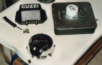
Anyway, I’m supposed to be writing about the car. I hope that’s why you’re reading this. I didn’t feel like working hard one day so I made a nice polished stainless steel VIN data plate to replace the aluminum one that came with the car. Uncle Sam says that it can be mounted on the driver’s door post, NOT. There is no door. Or it can be mounted on the dash by the front window, NOT. There is no front window. It could also be mounted on the left side of the instrumentation panel, but my gizmos take up that space. The last and best option is the firewall which is where it will be mounted after painting the body.

After I trimmed and mounted the tail light fiberglass covers, I realized that the tail lights need spaced out in order to fit properly. Armed with fresh nylon spacers from the lathe and longer bolts from the candy store the lights fit better than the last piece of a jig saw puzzle.

I wish the same could be said for the tail section. Man, where do I start? Of all the pieces of the car, it was the hardest to fit. This is due to its size and the number of items that it must align to. I rough trimmed, mounted the hinges and installed six 90° quick release fasteners with only one problem. I couldn’t align the center of the rear tire to the center of the tail section without causing other alignment problems. I spent several days working out a compromise that I could accept. I ended up with several small misalignments rather than one large one. I don’t think any can be noticed with the naked eye.

Trimming around the gas cap and edge that that mates to the body was easy. The right rocker panel mated perfectly to the tail section, but the left was too long. I had to remove ⅛˝ off the rear end and move a large radius ⅛˝ forward. I next had to design a fastener to secure the rear of each rocker panel to the tail section. Reverting to flintstone building, I garnered that the original design intended to use 90° quick release fasteners. Unfortunately, they can’t work because there is nothing to secure them to due to the shape of the joint. I could see that the manufacture used a nut plate and bolt setup from underneath. While this is easy and secured the joint well, it would be difficult to reach for maintenance. It defeats the purpose of the six 90° quick release fasteners already installed. I made a fastener similar to the bolt used to secure the hood. It uses the same tool as the hood for removal and can be accessed from the side of the car. A spacer had to be molded into the tail section and custom bracket fastened to each rocker panel. It sounds easy, but that’s a Saturday and a half of work.

Next, I reinstalled the exhaust, which comes with the hangers welded on, and cut out the preformed hole in the tail section. The pipe wasn’t centered well in the hole. I didn’t want to move the hole, which would cause other alignment problems, so I broke the weld on the exhaust hanger, rotated the pipe about 2° and rewelded it. Now it’s nearly centered, but I had an ugly pipe staring at me. The decorative exhaust pipe tips for sale ether wouldn’t fit or I didn’t like them so I made one on the lathe.

The tail section has a molded depression for what I can only presume is a reflector since there are no pictures and one was not included in the kit. There is also a molded protrusion for a license plate light. I eradicated both of them and installed a separate license plate mount and light. I measured the clearances between the rear fender and tail section in both the extended and compressed positions to determine if adequate space exists for the bolt heads and wires from the license plate mount and light. The tightest potential gap was ½˝. I made several low profile fasteners to secure the license plate light wiring and molded them into the tail section.

After weeks of work on the tail section, it was nice to move on to other items. I again attempted to establish the best placement for the 5˝ marine stereo speakers. In short, there is no perfect place for them. This car is just too small. In the end, I decided to flush mount them directly behind the seats between the roll bars at the top of the access hole for storage. I cut out some molded in reinforcing plywood in order to position them as high as possible. Because I weakened the structure, I made the speaker mounts from thick stainless to restore the strength in that area. The only disadvantage was decreasing the size of the access opening to the storage cavity.

I made the necessary parts to secure the throttle cable then started on the windshield. I don’t know what it’s made of, but it sure cuts, sands and feels like polycarbonate. I thought it was going to be real cheesy because it snaps on, but it’s actually very nice and solid. It extends 3˝ above the cockpit edge. I can see that it will provide much more wind and rain protection for the occupants.

I finished installing the cockpit trim. It went pretty smooth except I had to add two mounts to secure the panels in the rear corners.
 
Back
Top