• Ciao Guest - You’ve landed at the ultimate Guzzi site. NEW FORUM REGISTRATIONS REQUIRE EMAIL ACTIVATION - CHECK YOUR SPAM FOLDER - Use the CONTACT above if you need help. New to the forum? For all new members, we require ONE post in the Introductions section at the bottom, in order to post in most of the other sections. ALWAYS TRY A SEARCH BEFORE STARTING A NEW TOPIC - Most questions you may have, have likely been already answered. DON'T BE A DRIVE-BY POSTER: As a common courtesy, check back in and reply within 24 hours, or your post will be deleted. Note there's decades of heavily experienced Guzzi professionals on this site, all whom happily give endless amounts of their VALUABLE time for free; BE COURTEOUS AND RESPECTFUL!
  • There is ZERO tolerance on personal attacks and ANY HYPERLINKS to PRODUCT(S) or other competing website(s), including personal pages, social media or other Forums. This ALSO INCLUDES ECU DIAGnostic software, questions and mapping. We work very hard to offer commercially supported products and to keep info relevant here. First offense is a note, second is a warning, third time will get you banned from the site. We don't have the time to chase repeat (and ignorant) offenders. This is NOT a social media platform; It's an ad-free, privately funded website, in small help with user donations. Be sure to see the GTM STORE link above; ALL product purchases help support the site, or you can upgrade your Forum profile or DONATE via the link above.
  • Be sure to see the GTM STORE link also above for our 700+ product inventory, including OEM parts and many of our 100% Made-in-SoCal-USA GTM products and engine kits. In SoCal? Click the SERVICE tab above for the best in service, tires, tuning and installation of our products or custom work, and don't miss our GT MotoCycles® (not) art on the BUILDS tab above. WE'RE HERE ONLINE ONLY - NO PHONE CALLS MADE OR RECEIVED - DO NOT EMAIL AND ASK QUESTIONS OR ASK TO CALL YOU.
  • Like the new V100, GuzziTech is full throttle into the future! We're now running on an all-new server and we've updated our Forum software. The visual differences are obvious, but hopefully you'll notice the super-fast speed. If you notice any glitches or have any issues, please post on the Site Support section at the bottom. If you haven't yet, please upgrade your account which is covered in the Site Support section or via the DONATE tab above, which gives you full site access including the DOWNLOADS section. We really appreciate every $ and your support to keep this site ad-free. Create an account, sign in, upgrade your account, and enjoy. See you on the road in 2024.

nevada 750 clutch / flywheel

scotto

Just got it firing!
Joined
Sep 15, 2010
Messages
4
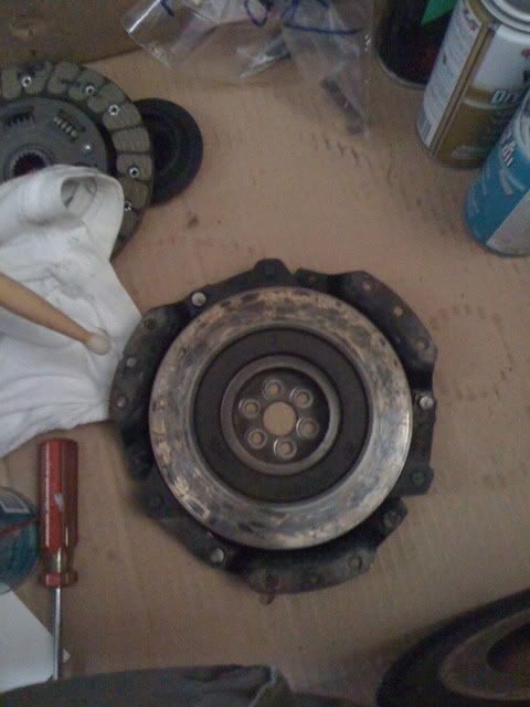
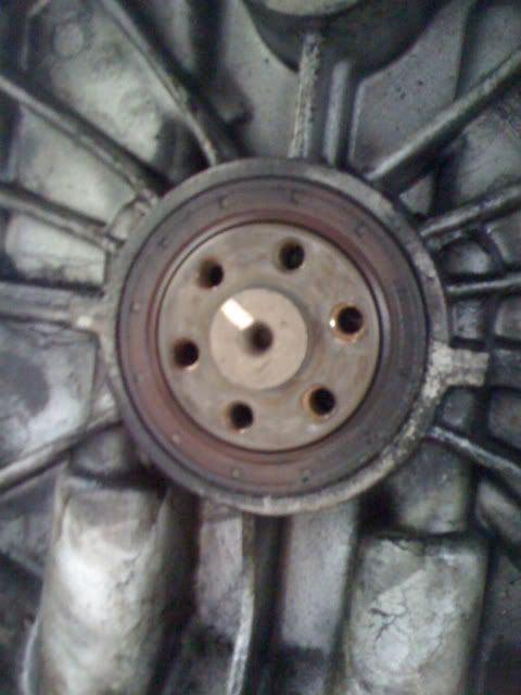
How do I re-set the position of flywheel (the one with the position sensor "lumps cast in to it) positioning was lost when the clutch was removed and there are no marks in the clutch/crankshaft bolting area to line up to. Can I set the engine to tdc on one cylinder and take it from there? What ones of the "lumps on the flywheel relate to tdc? help please.
 
What year is the Nevada?
If it has the same flywheel as a 04 Breva these pics may help. One of the brackets on the flywheel that the ring gear bolts to has a notch in it (indicated with drumstick) that gets lined up with the yellow mark on the crank face. The crankface is hidden from view unless the pressure cup is removed form the center of the flywheel. If the flywheel was not removed from the crank when the clutch was done it should still be in the right place.

1284647087.jpg


1284647238.jpg


Hope that helps.
 
Hi Nolaguzzi, thanks for your reply appreciate you taking the time. The bike is a 1997 model but the clutch in your picture appears to be identical to mine.

Unfortunately on my machine there are no marks on the back end of the crankshaft so I have the choice of 6 different positions for the clutch relative to the crankshaft and another 3 for the flywheel itself! I was wondering if anyone knew which of the "lumps" on the flywheel are TDC for whichever cylinder - there are 4 lumps, one of which is a double. I'm puzzled by this as there are only 2 cylinders so why the 3 singles and a double? I would have thought that all that was needed was one trigger for each cylinder - any ideas?
 
Sorry scotto I could only offer conjecture at this point as I only know a little about my specific bike. Hopefully someone else will chime in. I will be curious how you get this figured out. Surely someone else has gone through the same thing. Good Luck!
 
The white mark is where the crank pin is located. Get a piston to TDC (cycle stroke doesn't matter). Mark the crank in line with the cylinder that is at TDC.
 
Hi John zibell, thanks for that - should have realised that myself as it's obvious now that you mention it. Still leaves the question of which of the 4 cast on lugs on the flywheel relates to the firing position for which cylinder - any info on that?
 
Hi Guys, following John's comments I think I've sorted the timing issue but won't know for sure until I'm in a position to start the engine. I thought a little bit of history as to why the clutch was removed in the first place might be of interest. A few weeks back I tried starting the bike after work and the starter engaged for about 1/2 to 1 revolution and then disengaged itself but kept on turning while I kept the starter button depressed. Tried several times to start up but got the same result every time, eventually managed to bump start down a steep hill. Naturally I suspected the starter and removed it when I got home. I reconnected the starter and held it against the crankcase whilst operating the button and it appeared to be working perfectly. I then had a look at the flywheel through the starter opening and noticing a few shiny burrs on the teeth of the flywheel. I worked it round with a screwdriver and was surprised to find that the gap (in an axial direction ie along the crankshaft centreline) between the flywheel and the casing varied as it was rotated. Stripped the bike down, removed the clutch and discovered that the centre of the clutch housing where it is bolted to the crankshaft was distorted so that the plane of the clutch was about 5-6 degrees from being perpendicular to the crank. Ever since I've been trying to figure out how it got into that shape! The new clutch has now been fitted (hence my earlier questions (I know, I should have marked the positions on disassembly) but the starter is performing as it did earlier - 1/2 to 1 rev then disengaging but the interesting thing is that when the plugs are removed and the starter engaged it will go on turning the motor without disengaging until I take my thumb off of the button. I realise that it will be easier for the starter to turn the motor with no compression on it but why not with the plugs in? The starter has been stripped down and I can see nothing untoward inside and the battery is in good condition and fully charged. Could it be a faulty solenoid not holding the pinion fully in or maybe the starter motor itself has somehow lost power (the relays seem ok). Your thoughts on the starter issue and why the clutch distorted in the way it did would (as you might imagine!) be very welcome. There appears to be an obvious link-misbehaving starter maybe forcing the flywheel over and distorting the clutch housing (would take a heck of a force to do so given that the clutch housing is about 4mm thick at the bolting area) but sustaining no obvious damage itself. It has got me baffled and I'm lying awake at night thinking about it!! Your comments please folks!!
 
Back
Top