• Ciao Guest - You’ve landed at the ultimate Guzzi site. NEW FORUM REGISTRATIONS REQUIRE EMAIL ACTIVATION - CHECK YOUR SPAM FOLDER - Use the CONTACT above if you need help. New to the forum? For all new members, we require ONE post in the Introductions section at the bottom, in order to post in most of the other sections. ALWAYS TRY A SEARCH BEFORE STARTING A NEW TOPIC - Most questions you may have, have likely been already answered. DON'T BE A DRIVE-BY POSTER: As a common courtesy, check back in and reply within 24 hours, or your post will be deleted. Note there's decades of heavily experienced Guzzi professionals on this site, all whom happily give endless amounts of their VALUABLE time for free; BE COURTEOUS AND RESPECTFUL!
  • There is ZERO tolerance on personal attacks and ANY HYPERLINKS to PRODUCT(S) or other competing website(s), including personal pages, social media or other Forums. This ALSO INCLUDES ECU DIAGnostic software, questions and mapping. We work very hard to offer commercially supported products and to keep info relevant here. First offense is a note, second is a warning, third time will get you banned from the site. We don't have the time to chase repeat (and ignorant) offenders. This is NOT a social media platform; It's an ad-free, privately funded website, in small help with user donations. Be sure to see the GTM STORE link above; ALL product purchases help support the site, or you can upgrade your Forum profile or DONATE via the link above.
  • Be sure to see the GTM STORE link also above for our 700+ product inventory, including OEM parts and many of our 100% Made-in-SoCal-USA GTM products and engine kits. In SoCal? Click the SERVICE tab above for the best in service, tires, tuning and installation of our products or custom work, and don't miss our GT MotoCycles® (not) art on the BUILDS tab above. WE'RE HERE ONLINE ONLY - NO PHONE CALLS MADE OR RECEIVED - DO NOT EMAIL AND ASK QUESTIONS OR ASK TO CALL YOU.
  • Like the new V100, GuzziTech is full throttle into the future! We're now running on an all-new server and we've updated our Forum software. The visual differences are obvious, but hopefully you'll notice the super-fast speed. If you notice any glitches or have any issues, please post on the Site Support section at the bottom. If you haven't yet, please upgrade your account which is covered in the Site Support section or via the DONATE tab above, which gives you full site access including the DOWNLOADS section. We really appreciate every $ and your support to keep this site ad-free. Create an account, sign in, upgrade your account, and enjoy. See you on the road in 2024.

New Stelvio arrived

Assuming the on was with the bike actually running....just to be sure.

If it was with the bike running then you are correct, it is not transferring power from the 87A terminal (middle on you diagram) to the 87 terminal (far right). It looks like it is getting power from the 30 amp fuse (terminal 30.. far left terminal on your drawing) and that the trigger is getting power (86... bottom terminal on your drawing). Can't believe both relays show the same thing. If the trigger terminals (86 and 85) have power, the relay has to fire.


Your relay is not working. Easy way to test that it is the relay it put a wire jumper between terminal 30 and 87 (far left and far right terminal in your drawings) and then start the bike (can insert a wire to the back of the relay plug). If it is the relay the charging should start and the lights come on when you start it.

The trigger is getting power but it is not flipping the contact. May just need a good tap on the side. They do get stuck. Try taking it apart and see if you can see something obvious. May just need a cleaning. Either way, get a new one as it is trash.
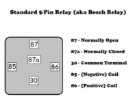
Upload 2017 1 1 14 29 17
 
I was testing with the key on but not running. In any case I went to NAPA today (Echlin, known good stuff) and got a new one, cross referenced to Bosch 0 332 209 151, and threw it in., and neither does it charge nor do the lights work if I put it in the HB location.

I did find the oddest thing. With the bike running , relay in the lighting logic position, 30common is not getting current. I can't get my mind around that can anyone? That explains why it isn't working but how is it possible?
 
Last edited:
The HB location is the wrong location. You need to put it in the lighting relay location. That is the one that drives the lights and the charging.

You need to check all the conditions with the bike running. These relays do not trigger unless the bike is actually running. It makes sense that you did not get anything on the 30 terminal on the HB relay when the bike was running if the lighting relay is not working. Replace the lighting relay with the new relay and see what happens. Forget about the HB relay for now. Just get the charging working then you can figure out if you have a problem with HB.
 
Also check the main fuses. By the schematic they are the source for pin 30. There have been cases where the fuses are good, but the fuse holder is defective.
 
Also check the main fuses. By the schematic they are the source for pin 30. There have been cases where the fuses are good, but the fuse holder is defective.

John, that was why I had him check for voltage at the relay itself. His previous post indicated that he had voltage at the 30 terminal. I suspect there is confusion between the lighting relay and the HB relay. The High Beam (HB) relay does not get power to 30 unless the lighting relay is first triggered. The diagram is wrong as it shows the HB relay on the Stelvio as a 4 pin and it is actually a 5. It follows the same relay logic as the Norge.

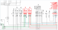
This is what is should look like. In the diagram below, 6 is the lighting relay and 5 is the HB relay. Terminal 30 on the HB relay is triggered from Terminal 87 of the lighting relay which is triggered when the bike is started, and also sends power to the exciter on the generator. The power from the lighting relay comes from the infamous 30 amp fuse.

Upload 2017 1 2 11 23 18

It was discussed and verified in this thread....

https://www.guzzitech.com/forums/threads/2012-ntx-lighting-relay-logic.13928/
 
I'd been doing all my checking yesterday on the Lighting relay with the key on, not running. It turns out the HB has no power at all, key on only or running, with the handlebar switch in either position, period. The Lighting relay has power at 30 with the key on but none when running. All very confusing.
 
Last edited:
Agreed, confusing. Make no sense, at least by the logic that every other Stelvio runs by. I am not sure what else to tell you other than you have an electrical gremlin (which I am sure you have already figured out). At this point, I would just verify that you are looking at the right relays. Perhaps your bike has them in a different order for some reason and we are looking at the wrong relays. If you pull the relay, it should have the terminal numbers on the bottom. Make sure you are probing the right terminals. Only other relay to check is the maintenance relay. It is basically a relay that the lighting relay sends power to on the 87A terminal. It is there to verify to the ECU that there is enough power to start the bike otherwise it will not start. If it was faulty the bike should not start, but it has been known to do some weird things if they are a little flaky.

Failing all that I am not sure what to tell you. The problem is definitely the lighting relay not getting power, but make no sense that the supply power goes away when you start the bike. Starting the bike should flip the relay to terminal 87 and everything should fire up. You either have a short somewhere or there is something going on with the ignition switch.

When the power drops from terminal 30, pull the 30 amp fuse and see if there is power to ground on one side. If not, there there is something amiss with the ingnition, if there is power, then you may be looking at the wrong relay, but without being there to do the diagnostic it is difficult. You just need to keep poking and prodding with the multi-meter, or you may end up having to take it to a dealer.
 
Hi. After reading through this whole thread, I'm not convinced that the original poster is looking at the correct fuses. I could be wrong, but here are the pages from the Owners manual for reference. Maybe it will help out some.

Auxilary%20fuses.png


Main%20fuses.png


Also, there is a factory voltage meter built into the instrument display. You access it by using the MODE button on the left handlebar. (Long held movements of the MODE switch, left or right, change between the 3 default screen modes, while short quick movements of the MODE switch, switch between the options of the particular screen mode. i.e. Each screen mode has multiple options within itself.)

If after turning on the ignition and after the instrument initialization screen, in the lower right hand corner of the screen you see a 1, then you are in the tripmeter settings for TRIP 1 so push the MODE button to the LEFT and hold it there for approximately 1.5 seconds until the screen displays ATC and then quickly release the switch.

If after turning on the ignition and after the instrument initialization screen, in the lower right hand corner of the screen you see a 2, then you are in the tripmeter settings for TRIP 2 so push the MODE button to the RIGHT and hold it there for approximately 1.5 seconds until the screen displays ATC and then quickly release the switch.

Now that you are at the ATC screen, quickly press the MODE button once to the left. Your screen should now display the battery voltage that the ECU is seeing. It will stay on this screen after starting and will display increases in voltage up to about 14.2-14.4 if the throttle speed is raised.

Please check the pages I have posted for you to be sure you are looking at the right fuses, and that they are of the correct amperage. Also, they are blade fuses which are cheap, and I have learned long ago, to have spares because sometimes there can be a break in the fuse which is not easily visible. You can also check each fuses continuity with your external voltmeter to be sure.

Perhaps this will help.

Good Luck!

Scott
 
I thought of something else that might help you too. On this site is the following detailed procedure which I wrote up.

https://www.guzzitech.com/forums/threads/charcoal-canister-removal-detailed-with-pictures.9202/

Along with highly detailed instructions for the removal of the front cowling and light assembly, it contains this picture which shows the connections for the headlights both from the main wiring loom and the sub-connectors to the lights themselves!

You may wish to check to be sure these connectors are even connected. If the nose of the motorcycle had been removed for any reason, then this connector would have been unplugged and possibly is still unplugged, thereby causing your issue. It's worth a look.

Good Luck!

CharcoalCanisterRemoval37_800x600.jpg
 
Scott. Fully agree on the wrong fuse scenario. I posted pictures of the panel that needs to removed below the seat in the hopes that would guide him properly and the report back is that they are looking at the correct fuse.

All that being said…

Rapier, the 30 amp fuse that you are looking at is in a holder with another fuse. Is that fuse a 20 amp or a 40 amp. It needs to be the fuse that is paired with the 20 amp. That is another possible scenario that may cause what you are seeing but we ruled that out as the reported 30 amp was good. Please verify.
 
I think you and I are on the same page Joe.

Yet another tidbit just popped into my head. Rapier wrote the following:

"Probably irrelevant back story. I had the local dealer run the VIN before I bought it and it said the timing sensor had been replaced under warranty."

I would be willing to bet that whoever did this procedure, removed the bodywork and possibly the front nose/lights assembly. I would not be the least bit surprised if the connector was simply unplugged, which would explain all of this.

Also, he can check alternator output by using the dashboard voltage gauge as I described. If there is voltage increase, then the likelihood of a wiring loom issue or both relays being bad, seems astronomically rare to me.

If I was in the guy's garage I would proceed as follows:

1. Remove the large rubber front plug with the Moto Guzzi Eagle it in the very front of the engine on the alternator belt cover, and stick your finger in there to the side and verify the belt is there and under tension. If this checks out, go to the ATC menu on the dashboard and move to the internal voltage meter display on the information display (detailed instructions provided in earlier post), note the initial voltage and start the bike and read what the dashboard voltage reading is saying at idle and then at 3000 rpms. See if the voltage increases with increased rpms. If it does, the alternator is fine.

If the indicated voltage does not increase with rpm, then you more than likely have a blown fuse in the main panel, fuse #1 40A. I have experienced this firsthand when mine blew once and I ran a straight discharge for 30 miles to get home, watching the voltage on the dashboard display slowly drop .1 volt at a time.

If that fuse is okay, then with the bike off again, check the auxiliary fuse #A (which is #1 [15A] in the fuse box - see photo).

CHECK FUSES with an Ohm meter for continuity. Don't rely on visual inspection.

NOTE: The book lists the amperage values for slots A-G on the auxiliary fuse panel as 15A, 15A, 10A, 15A, 15A, 3A, 5A, however, my photo from my bike which is OEM factory unchanged in any way, the slots are labeled 1-7 and are respectively 10A, 10A, 10A, 15A, 15A, 3A, 5A. Go figure. I decided to leave mine alone because I've never experienced a blown fuse except in the first month of ownership due to the crap running lights that are way to hot and shorted out the wiring, blowing Fuse #1(40A) from the main panel, and I like the idea of blowing at a lower amperage than a higher one.

If those fuses check out ok, then also check each of the other fuses in both the main and the auxiliary panel for correct amperage and continuity utilizing a volt/ohm meter. 5 minutes work for peace of mind where you will know that all of that is in good working order.

DSCF0185.jpg


CharcoalCanisterRemoval69_800x600.jpg


If all of that checks out, then we know we have a working alternator, a working fuse and fuse box, and a working wiring loom so far. My next suspicion would be a disconnected connector from previous warranty work. So...

2. Check that light connector to the major wiring loom I showed you in my earlier post picture. That connector runs power to both headlights as well as the small running light bulb. That's 3 lights in the nose that should be working but you say they aren't.

3. Check for power coming to the low and high-beam headlight bulbs with a voltmeter. Although not likely, both bulbs could have been blown somehow. Remember, there is also a running light bulb in that same nose housing that should be on as well. The odds of all 3 bulbs being blown would be astronomical I would think but I would check that before chasing relays.

Whew, sorry for the book.

I hope this helps him!

Good luck!

Scott
 
Last edited:
I was hoping it was that connector in the front cowl but no dice. Both relays have now been replaced but since HB has no current........... Yes I am checking the proper fuse and confirmed it was hot. I checked the other two in that location and the two on the block behind the positive battery terminal.


The little running lights along side the headlights do work. I mentioned that when the headlight dimmer switch is pressed on the left end, for a flash I guess, the dash shows the blue headlight symbol but it shows at no other time.

As I always say, I don't believe in electricity so I'm adverse to working on this stuff. Well in my old age i hate to work on my bike period, I want to ride. I'm a machine builder but no longer love to pick up tools if you get my drift. I'll dive in again this weekend. My eyes glaze over looking at schematics but I'll have to start being systematic about this.

Thanks for the help so far. I doubt in the end it will be all that big a deal to fix. Probably something stupid. As I say the thing seems perfect in every other way. I do have a few other questions but they can wait.

I retire at the end of May and will be doing a lot of traveling this summer so 6 months to get it all right, so no sweat. It's probably 10 weeks minimum to any riding weather at all here in Michigan anyway.

Bob Pierson
 
Last edited:
Bob, you will figure it out and your right, it will be something small. When the bike is running, the blue flashing light when you pull the HB switch, the little lights working in the front, lack of charging, no headlights and no power to the HB relay are all caused by a lack of power to the lighting relay (the 30 amp fuse power and the 30 terminal on the lighting relay). The lighting relay supplies power to the HB relay. No power at the lighting relay, no power at the HB relay. That is normal. There is no other possible cause that I can think of that has all those symptoms.

I am now starting to think that your relays may be in different spots and we may be barking up the wrong tree so to speak.

What are the wire colors of the lighting relay and the HB relay. Once you get me those I will confirm that with my bike as I know the wiring diagram has the wrong colors. Also, pull the relay out of the plug and look at the bottom of it where the terminals all. The terminal numbers will be there. Let me know the terminal numbers and corresponding wire colors. That will be the only way we will know for sure what is happening. When you get me that information we can trouble shoot it with actual wires.

I am not giving this up as long as you are willing to keep at it.
 
Damn. I thought we might get off easy. I don't know where in Michigan you are, but I'm right by Toledo if that's anywhere close. When the weather gets a bit nicer, I have a full commercial setup and a bike trailer where we could get the bikes side by side and go at it. Probably Joe will get you through it much sooner though, but the offer is on the table for you if you need it later!

Good Luck!
 
Bob, just had a thought. When you tested the relays for power did you use a test light or a multimeter. The test light will tell you if there is some power and continuity, but won't necessarily tell you there is enough power. Also these relay connections can back feed small voltages from other sources once the bike gets running or just the key is on. Do you actually have 12+ vDC in your tests??
 
I was using a mulitmeter. I did note some voltage drops at some terminals on the Lighting relay into the 8V range but not sure it was relevant. Every contact I have seen looks clean and nice and I've spray cleaned them anyway. To repeat, every other function on the bike seems fine including all the menus on the dash, all other lights, horn, and it runs fine.

The wire on HB 30 is, to me, white and thick black stripe. I'm slightly color blind. I'm stumped on the schematic as to were that wire comes from. I had thought of just doing a jumper to it and see if everything works but it probably will. I need to know the route of that power to HB 30 from the fuse block.

Again I am certain that there is power to the fuse block and the fuse is good. I need to know where it goes from there and find the disconnection or fault before it gets to the HB relay.
 
Last edited:
The wire from the 30 amp fuse runs to terminal 30 on the lighting relay. It does not run to the HB relay. The HB relay is fed power from the lighting relay from the 87 terminal which also feeds the exciter on the alternator and charges the battery. This only happens when the bike is running, not just just with the key on. Without the exciter power, the alernator is dead. The lighting relay is the start of all the power. If you are not charging, unless your alternator is dead of the belt is gone, the lighting relay is the cause along with the lack of lights, HB or LB as it supplies power for both.

The LB headlights get power from the 87a terminal on the HB relay. When you flip the HB/LB switch, the HB relay flips from 87a to 87 and then feeds the HB side of the light bulbs and turns off the LB.

A reading of 8vDC is backfeed voltage to the relay and not primary voltage from the 30amp fuse. You need at least 12vDC for a proper connection.

I will take a look tomorrow at the wire colour for the HB relay. What is the colour of the terminal 30 wire on the lighting relay. I would not worry about the HB relay yet. Concentrate on getting the lighting relay to work as that is the start of the power series and responsible for charging in all the lighting power. Once the lighting relay is working, then we will see if there is an issue with the HB relay.

Measure the voltage to ground on terminal 30 of the lighting relay when the bike is running. Going to state the obvious and please forgive me, but make sure the meter is set to DC voltage. That is the only way we will know what is happening. If there is power, then measure the voltage to ground of the middle terminal 87A and also voltage to ground of 87 (opposite end of relay from terminal 30). Make sure the bike is running when you do this. From those three voltages we will know what the issue is.
 
Last edited:
Well I had thought it was Lighting>HB but somehow got sidetracked to looking just at the HB, which is where I discovered it is cold under all conditions.

Lighting relay 30 wire is green, of all things. I should have noted which terminals had the voltage drop but didn't. It's barely been above single digits here all week and I'm not starting or working on it until it warms up some. I am out of town for the coming week.
 
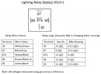
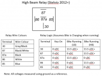
Here are the wire colours from my 2012 Stelvio and the relay logic that was confirmed. Your colours should be the same. Lighting relay is farthest to the rear of the bike, HB relay is second from the front of the bike. Exactly as it is indicated in the picture in the earlier post.

If your HB relay is cold on all terminals when the bike is running then the power is not being supplied to the lighting relay (assuming your LB lights and charging is still an issue). You need to review what is happening with your lighting relay using the pictures below as the reference. Don't worry about the HB relay for now.

What is the voltage with just the key on and then with the bike running for the lighting relay for each terminal. Easy enough to just probe the bottom of the plug. I use the valve cover bolts as ground. Makes sure all your voltages are measured with ground as the reference, not across terminals. Report back and then we will see what the issue is.

Upload 2017 1 7 17 15 15 Upload 2017 1 7 17 15 57
 
Back
Top