zoom zoom
Tuned and Synch'ed
Tonight, more progress has been made with the installation. I will describe each pic as I go. So far, I have only used parts included in the kit.
Because it was necessary to use up the cable length on the servo, I determined it was better to route it out the right and cross over.
Where I crossed over was behind the airbox.
The next image shows the bracket. I needed to cut a bit off and put a 90 in it.
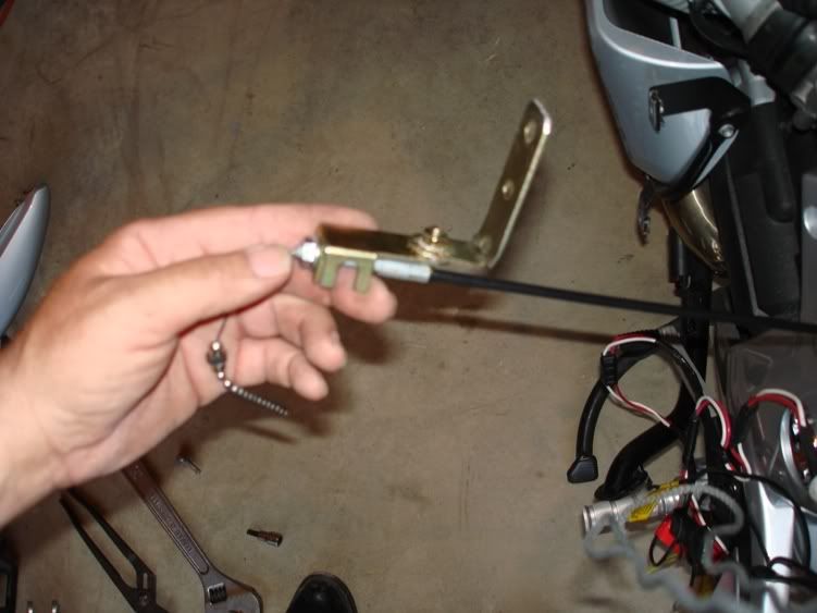
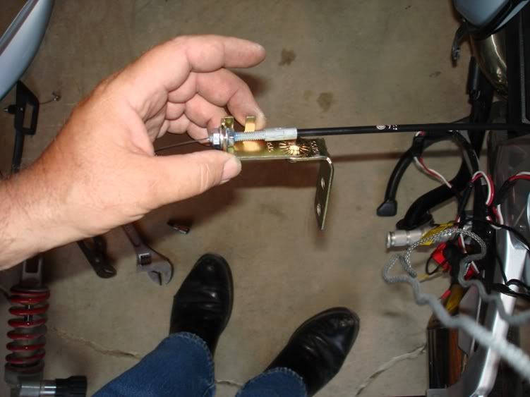
This is another angle of the same bracket. I secured the cable as near its end as possible. Then I put blue locktite on the threads to prevent the nuts from backing off.
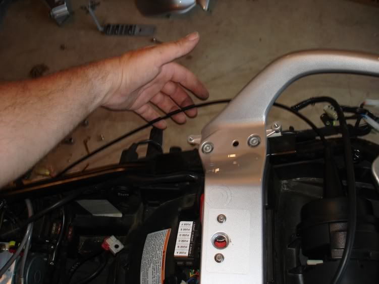
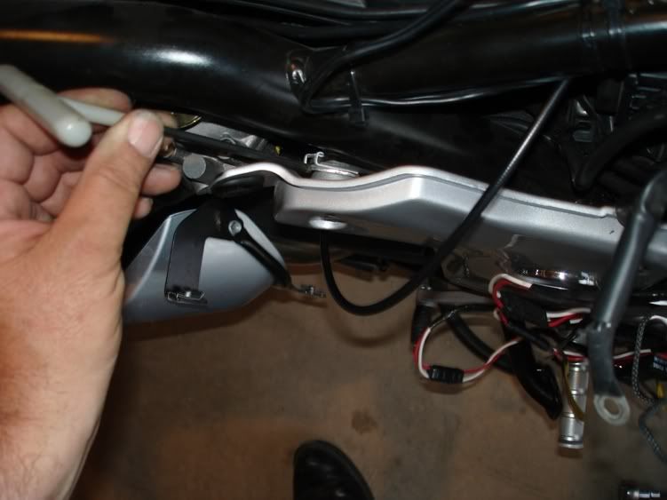
This is where I attached the bracket. I removed the front top bolt and loostened the top rear bolt. I was able to flex the side piece enough to sandwich the bracket in between it and the frame. I was able to reuse the original bolt. My T wrench is pointing at the bracket mounted in place.
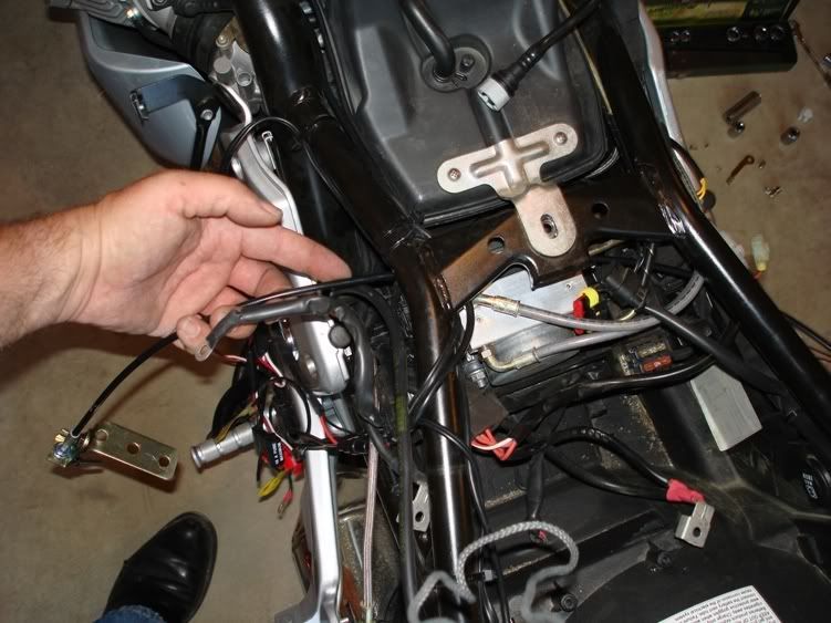
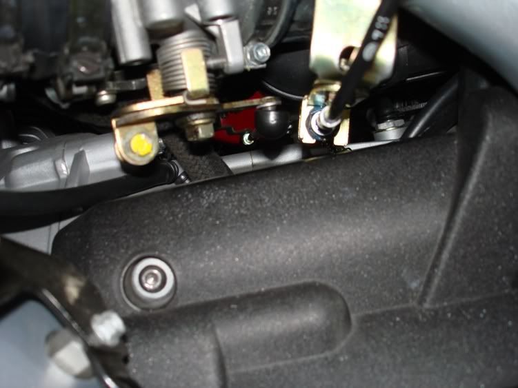
This shot shows the cable in its final position. In alignment with the throttle linkage that ties the two TB's together. That is where I intend to pull from. This is viewed from above the starter.
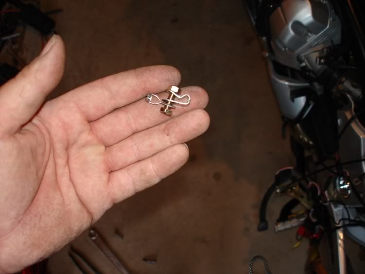
These are the pieces I'll use to attach to the linkage rod and cruise chain.
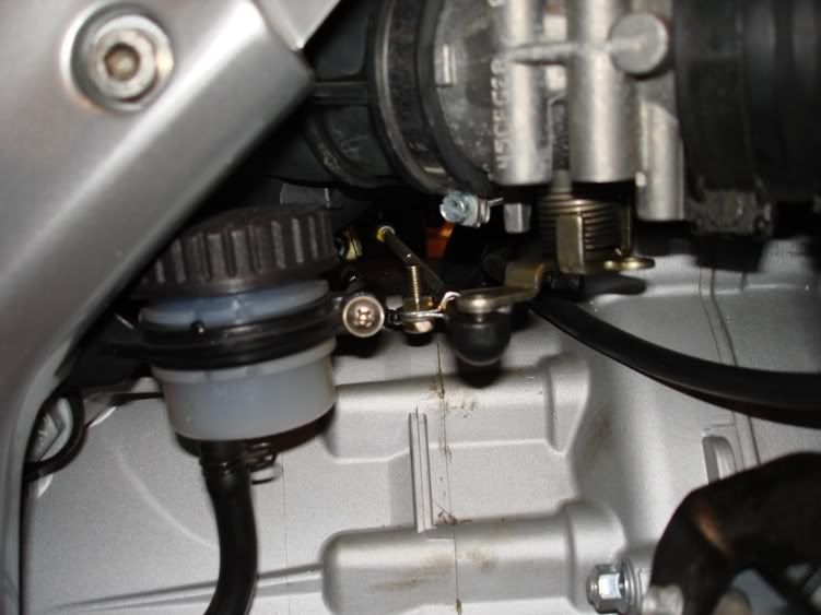
This last pic is the other side looking at the attaching hardware on the linkage rod. I clamped it just behind the threads used for adjustment. I used 15 links in the ball chain. That includes the end links.
As it stands, there is nothing the chain could get caught on that could cause unfavorable things to happen. Next will be the vacuum cannister, switch waterproofing/ mounting, wiring, and brake light relay because of the LED's. Stay tuned.
Zoom Zoom,
John Henry
Because it was necessary to use up the cable length on the servo, I determined it was better to route it out the right and cross over.
Where I crossed over was behind the airbox.
The next image shows the bracket. I needed to cut a bit off and put a 90 in it.
This is another angle of the same bracket. I secured the cable as near its end as possible. Then I put blue locktite on the threads to prevent the nuts from backing off.
This is where I attached the bracket. I removed the front top bolt and loostened the top rear bolt. I was able to flex the side piece enough to sandwich the bracket in between it and the frame. I was able to reuse the original bolt. My T wrench is pointing at the bracket mounted in place.
This shot shows the cable in its final position. In alignment with the throttle linkage that ties the two TB's together. That is where I intend to pull from. This is viewed from above the starter.
These are the pieces I'll use to attach to the linkage rod and cruise chain.
This last pic is the other side looking at the attaching hardware on the linkage rod. I clamped it just behind the threads used for adjustment. I used 15 links in the ball chain. That includes the end links.
As it stands, there is nothing the chain could get caught on that could cause unfavorable things to happen. Next will be the vacuum cannister, switch waterproofing/ mounting, wiring, and brake light relay because of the LED's. Stay tuned.
Zoom Zoom,
John Henry