• Ciao Guest - You’ve landed at the ultimate Guzzi site. NEW FORUM REGISTRATIONS REQUIRE EMAIL ACTIVATION - CHECK YOUR SPAM FOLDER - Use the CONTACT above if you need help. New to the forum? For all new members, we require ONE post in the Introductions section at the bottom, in order to post in most of the other sections. ALWAYS TRY A SEARCH BEFORE STARTING A NEW TOPIC - Most questions you may have, have likely been already answered. DON'T BE A DRIVE-BY POSTER: As a common courtesy, check back in and reply within 24 hours, or your post will be deleted. Note there's decades of heavily experienced Guzzi professionals on this site, all whom happily give endless amounts of their VALUABLE time for free; BE COURTEOUS AND RESPECTFUL!
  • There is ZERO tolerance on personal attacks and ANY HYPERLINKS to PRODUCT(S) or other competing website(s), including personal pages, social media or other Forums. This ALSO INCLUDES ECU DIAGnostic software, questions and mapping. We work very hard to offer commercially supported products and to keep info relevant here. First offense is a note, second is a warning, third time will get you banned from the site. We don't have the time to chase repeat (and ignorant) offenders. This is NOT a social media platform; It's an ad-free, privately funded website, in small help with user donations. Be sure to see the GTM STORE link above; ALL product purchases help support the site, or you can upgrade your Forum profile or DONATE via the link above.
  • Be sure to see the GTM STORE link also above for our 700+ product inventory, including OEM parts and many of our 100% Made-in-SoCal-USA GTM products and engine kits. In SoCal? Click the SERVICE tab above for the best in service, tires, tuning and installation of our products or custom work, and don't miss our GT MotoCycles® (not) art on the BUILDS tab above. WE'RE HERE ONLINE ONLY - NO PHONE CALLS MADE OR RECEIVED - DO NOT EMAIL AND ASK QUESTIONS OR ASK TO CALL YOU.
  • Like the new V100, GuzziTech is full throttle into the future! We're now running on an all-new server and we've updated our Forum software. The visual differences are obvious, but hopefully you'll notice the super-fast speed. If you notice any glitches or have any issues, please post on the Site Support section at the bottom. If you haven't yet, please upgrade your account which is covered in the Site Support section or via the DONATE tab above, which gives you full site access including the DOWNLOADS section. We really appreciate every $ and your support to keep this site ad-free. Create an account, sign in, upgrade your account, and enjoy. See you on the road in 2024.

Safety Alert for 8V Motors. Possible Alternator Wiring Short

canuck1969

GT Reference
GT Contributor
Joined
May 31, 2012
Messages
1,242
Location
Burlington, Ontario
All,

Going to come out of the dark for a bit as I feel it is important to communicate a recent finding on a 2013 Stelvio with apparent charging issues. This could easily be an issue on any other 8V motor so not specific to the Stelvio.

Please don't respond with not possible or try to argue any facts on the notes below. This is from first hand experience with the bike and seeing it with my own eyes and testing it with my own meter. All the electrical paths in my previous thread concerning the lighting relay and HB relay are verified accurate so please don't tell me something that is not there like the HB handlebar switch is responsible for charging issues.

One of the members on the forum (I will leave it to him if he wants to be identified) contacted me via PM as he had a charging issue with his bike. SInce I had laid out the electrics in a previous thread he thought I could help him with fixing his bike.

Symptoms

  • Had no headlights, high beam or low beam with the bike running, however from time to time they would come on.
  • When headlights did work, there was no charging or the voltage was at a very low level (ie 12V or so) but did not seem to go lower.
  • No charging with headlights on or off
  • This continued sporadically for some time but the bike never died or left him stranded.
  • Replace the battery with a MotoBatt but the problems still continued
  • Had the obligatory no head lights, no charging and blue HB light when the momentary HB switch was pulled.
  • 30 amp fuse was good.
At that time we suspected a faulty relay and he replace both the HB and LB relays with Bosch relays. The problems still continued. Over email, I requested the voltages to be measured at the relays as per my previous thread concerning the voltage sequencing of the HB and Lighting relays.

  • Voltages on terminal 30 and 87 on the lighting relay were sporadic. Voltage one minute, no voltage the next. Even when 30 (main relay power from 30 amp fuse) and 87 (exciter power and lighting power) had power there was no charging or lights which at that time seemed impossible for the lights as 87 is pretty much a direct line to the lights as long as the HB relay is working (and it was confirmed as working)

At this point I was intrigued and packed up my tools and electrical diagnostics and repair items. Luckily he was only an hour ride from my place.

I spent a hour or so testing and retesting the paths and nothing made sense at that time. The most curious thing was that when the bike was running, the power to the 30amp fuse (and therefore the lighting relay) was gone. When it was just the key on, the power was there.

  • Tested resistance of the 30 amp fuse power supply wire (red green) to the +ve on the battery and it had continuity (0.1 ohm resistance)
  • Tested continuity of the 40 amp fuse power supply (green/red) that is for the charging power to the +ve on the battery and it had a resistance of 280 ohm. This should be zero to the battery.
  • Tested continuity between the above two wires which are spliced together as some point (brings battery power and charging power to the bike) and had continuity.
  • Jumped power to the 30 amp fuse directly from the battery which powered the 87 terminal on the lighting relay (ie. power to headlights and alternator exciter) and the headlights came on when the bike was running, but no charging.
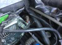
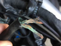
At this point we removed the tank. I tested continuity from the main power lead on the alternator to the battery and it had continuity. After scratching my head as it made no sense, I pull the boot back on the terminal and tested it again. Now it didn't have continuity. Wiggling the wire produced an on/off on continuity. I gave a small tug on the wire from the boot and out it came with a crunch and burnt copper wire everywhere. The member has photos of the wire and terminal.

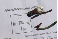
Turns out the splice between the 40 amp and 30 amp fuses is at the actual alternator. Both wires are crimped into a ring terminal that is screwed to the alternator. The ring terminal insulation was completely burnt along with about 2 inches of wire. Turned it to dust.

Had just enough connection to give readings when the key was on, but once the bike was started and the vibrations set in, the connection was broke. This resulted in increased resistance and a crap load of heat. If this had continued and not broken completely when the bike was running it would have resulted in a meltdown under the gas tank. He did say that he swore he saw some puffs of smoke on the last ride by though he was imagining things, as we all have. The crimp on the ring terminal was marginal at best. I am not even sure it was there to begin with. This was not a corrosion issue as the wires themselves and the insulation were completely burnt. There is also nothing to ground to where these wires are and they are protected by a long boot so it was not a small short to ground

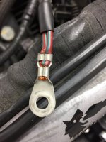
Installed a new ring terminal and made sure the crimp was secure. Fired up and had full charging and lights.

This is something to be aware of it you start to have charging and light issues and the 30amp fuse and relays are still good. Easiest check is to check the resistance between the 30 amp red/green wire (one behind the right hand panel under the seat) and the 40 amp red green wire (40 amp next to the air box). It should be pretty much 0 to 0.1 ohm. Then check the resistance of each of those wires to the +ve on the battery. Should again be 0 to 0.1 ohms. Any resistance much higher than those numbers (subtracting the resistance of the actual meter wires) indicate a problem developing and you should be checking that connection at the alternator.

Thanks

Joe
 
Last edited:
Unless you have the proper heavy duty tool for crimping these terminals, soldering is safer assuming it wets the wires well. You only need the slightest loose fit with crimping and you will get some resistance which will increase over time. This produces heat and you could see the result.
 
Fully agree Brian. The one at the alternator is not like the one at the battery. It is just a simple ring terminal and not a heavy duty terminal. I have a crimp tool and double and triple checked the crimp.

Have not had one come loose ever on my bike and trust me between my Cruise control, Tire pressure monitor, dual horns, GPS, voltage monitor, LED aux lights, hand guard lights, tail box lights, heated grips and heated seat I have a lot of crimped connections, but there is always a first time. ;)
 
If you have a good crimping tool then the chances are you will get a good connection. Many only have the very cheap plier type, and experience tells me these are far from perfect.
 
OK, finally got some pictures. Now that I can spend some time looking at these, corrosion may still be a suspect. The green powder is a good indication but have no idea why this particular terminal would experience this much corrosion. The rest of the bikes connectors are pristine. May be galvanic corrosion induced by the poor crimp in combination with heat from the increased resistance but pretty sure the terminal is copper also. Hard to say. If you look at the wires, one of them pulled clean out, while the other one tore out from corrosion and or heat so the original crimp is still suspect. The insulation burned clean off the wires in the actual terminal boot (not in picture). Looks like the original heat source was inside the terminal crimp. Draw your own conclusions on this one. Either way, could happen again so keep an eye on things.

When I crimped on the new terminal I shrink tubed it and wrapped it and the wire with rubber splicing tape so moisture will no longer be an issue if that was the original cause but not convinced that was it. Bit or a chicken an egg thing going on. Only time will tell.

Upload 2017 6 14 8 44 11

Upload 2017 6 14 8 44 31

Upload 2017 6 14 8 46 33
 
Last edited:
Thanks for the report. A friend of me had the same problem, 2009 Stelvio ABS.

bye
Pat

Thanks for posting Pat. I just posted to a thread from a few months ago on the same symptoms. At that time we didn't know where the splice was and just running a dedicated power wire to the 30 amp fuse solved the issue. It that case I suspect it was a clean break with no aftermath as we have seen here. Nonetheless hopefully the owner sees the note and investigates further. Starting to get that feeling that we may see more.

https://www.guzzitech.com/forums/threads/new-stelvio-arrived.16690/page-4
 
I am the one who had the symptom last winter on a purchased bike. I jumped a hot wire to the relay and 3500 mi later no issues. Am 1 week into a month on the road. Will take this under consideration
 
It's obvious I think that tank removal is needed to get at the connector?

Not eager to do this on the road and as I said I have 3500 miles on my kludge fix with no problems at all.
 
It's obvious I think that tank removal is needed to get at the connector?

Not eager to do this on the road and as I said I have 3500 miles on my kludge fix with no problems at all.

Yes tank removal is best. If you have not had any issues up to now I don't think it is rush as it was most likely a clean split. Again, assuming that this was your issue based on the same symptoms but it may not be.
Just keep an eye on your voltage. If it starts to drop then something is up.
 
Had to tidy up some wiring from my cruise control install so took my tank off today to take a look.

Everything looked good from the outside. When to pull the boot back and the terminal spun on the post. A few choice words came out of my mouth as I though it had ripped out but turns out the nut holding the terminal on the post was loose. Finger tight at best. That's not good.....

Pulled everything off the terminal (had shrink tube on the terminal and wire) and the crimp looks good. Wires didn't seem loose in the crimp but re crimped it just in case.

Wrapped the exposed parts in rubber splicing tape and made sure the nut was on tight. It is a Nylock nut but still worked its way loose over time.

Started the bike up and for once in a long time I had 14.1 V at the dash and 14.3 at the battery. I had been running 13.9 best for that last year or so. I assumed it was all the extra electrics I had put on, but nope, it was the loose nut.

The one thing I did notice is that there was no sign of corrosion what so ever. This is a 2012 with 55,000 km on it. The one at the beginning of this thread was a 2013 with 15,000 km that was bought later as a demo that had only 700km (not sure of the year it was bought).

I still don't think the 2013 was caused by just corrosion. I would have expected to see something on mine.


File 000 2
 
A slight aside to this specific topic, but it prompted me to check out the Norge charging. Woefully low volts on the battery so I started going through it. 40A fuse was tarnished so I cleaned that up. Then I went on to a three way spade connector. This was also bad so I took it apart and cleaned all parts, then squeezed the spring bits on the spades. It went together more firmly, and on checking the battery volts were much better with the engine running. But then I put my hand on the red/green wire that takes the charge to the battery. It was hot! Got my digital probe and found it was running at 74 degrees C. Checked along the wire in case the connector was doing this, but no nearer the fuse it was just as hot.
Seems to me that with the harnesses getting ever more complex, savings have been made by cutting the amount of copper used. Remember this alternator can put out 40 Amps, it takes quite a hefty cable to carry that without heating and this was after less than a minute.
Next project will be to replace the cable with something a bit heavier. I'm also wondering about the need for a fuse in there, those little spade terminals are not rated at 40 Amps.
 
40 amps is not the norm. Your battery must be near death to demand this amount of charge, possibly because of a history of bad connections in the charging circuit that you have described.

If the 40 amps doesn't reduce rapidly, then it's time for a battery replacement.
 
I didn't say it was the norm, I said the alternator was capable of producing 40 amps, but in that initial time after startup, with two headlights going etc, it will be putting out quite a bit to replenish the battery from the starter drain.
 
A slight aside to this specific topic, but it prompted me to check out the Norge charging. Woefully low volts on the battery so I started going through it. 40A fuse was tarnished so I cleaned that up. Then I went on to a three way spade connector. This was also bad so I took it apart and cleaned all parts, then squeezed the spring bits on the spades. It went together more firmly, and on checking the battery volts were much better with the engine running. But then I put my hand on the red/green wire that takes the charge to the battery. It was hot! Got my digital probe and found it was running at 74 degrees C. Checked along the wire in case the connector was doing this, but no nearer the fuse it was just as hot.
Seems to me that with the harnesses getting ever more complex, savings have been made by cutting the amount of copper used. Remember this alternator can put out 40 Amps, it takes quite a hefty cable to carry that without heating and this was after less than a minute.
Next project will be to replace the cable with something a bit heavier. I'm also wondering about the need for a fuse in there, those little spade terminals are not rated at 40 Amps.
Just to make sure everything is good check the resistance between that red/green wire on the 40 with the red/green on the 30 amp fuse behind the right panel. Then check it to the positive on the battery. I wouldn't expect it to be that hot. The wire is more than adequate for 40amps given the length is not that much.
 
Well I didn't bother with measuring the resistance, it's such a job getting the air box out, I ran a new wire through anyway, alongside the old, but about twice the cross sectional area.
Result? Immediately got 14.25 volts at tickover, previous best was 13.5 at all revs after I had cleaned up all the connectors. So clearly there was still some resistance in that old wire and connectors.
 
This is definetly a maintenance item now and something that needs to be checked. I am now seeing 14.3 at the dash on startup (14.5) at the battery after a few rides to charge up the battery. That was just from tightening the terminal at the alternator. I have not seen that number for years. Normal has been 13.8 at the dash.
 
Back
Top