Moto-Uno
High Miler
The tank side panels on my 2018 Eldorado do NOT have to be removed to remove the gas tank . Peter
Follow along with the video below to see how to install our site as a web app on your home screen.
Note: This feature may not be available in some browsers.
I am alittle late to the partyOK - finally got around to finishing this project. Here we go.
As many of us know, getting to the air filter in the California 1400 is very difficult and frustrating. I discovered this when fitting a replacement K&N air filter as part of installing Todd Egan’s fueling kit. Told myself at the time (two years ago) that I would someday replace the airbox with a pod filter, as was done with other Guzzis in my past.
Theoretically, a pod filter could be attached directly to the throttle body. That could work, but then you would have to remove the tank to be able to remove the filter for maintenance, or to replace it. Also, there just ain’t much room for the body of the filter in there between the wiring harness verticals, as you’ll see in the pictures.
I chose to use the stock design as guidance. The stock Cali1400 has a rubber tube clamped to the throttle body on one end, and the airbox on the other. So my approach was to use an aluminum tube in place of the stock rubber tube, and attach it to the throttle body using a rubber coupler/reducer, and clamp a UNI filter onto the other end.
Here’s how I went about it….
REMOVE THE AIRBOX
Here’s the airbox out of the bike (ignore the UNI next to it, as it is not the one I used)….
- Remove the fuel tank. Don’t forget to release the pressure in the line before attempting to disconnect the fuel line.
- Remove the right side cover.
- Remove the battery.
- Remove the blowby hose from the airbox at the connection on the top left front of the airbox. And while you’re at it, go underneath the bike and yank on the clear blowby collector hose to remove it from the bottom of the airbox. Easier now than later.
- Disconnect the airbox from the bracket - bolts on each side up top.
- Remove the wiring harness from the bracket thingy - two screws.
- Remove the bracket thingy - it will otherwise be in the way.
- Remove the bolts that secure the bottom of the airbox to the battery box just below the frame rails on each side. This was a surprise to me as it is not evident in the workshop manual (pages 168 and 169).
- Disconnect the tube connecting the throttle body to the airbox - there are clamps on each end. Remove the tube, making removal of the airbox much easier.
- OK - now wiggle and cajole that damn thing out of there. Throw it across the garage/shop - and swear at it if you like, as did I.

View attachment 16140
...and the and the void created by its removal…

View attachment 16141
...and the throttle body exposed…

View attachment 16142
ORDER PARTS
Your new intake system will need a rubber coupler/reducer that attaches to the throttle body, a tube to go from the coupler/reducer to a filter, a filter, and some clamps.
An angled tube and a straight filter is an option I did not explore, but would have if the clearance from the highest part of the filter to bottom of the front of the seat was any tighter. You may want to consider it.
- The coupler/reducer is 3 inches inside diameter (ID) on the throttle body end and 2 ¾ inches ID on the tube end. I used one from Spectre Performance that worked perfectly - part number 87831. You’ll need a couple of 3 inch clamps (they aren’t included with 87831), so order those as well. Spectre has them.
- The tube should be 2 ¾ outside diameter (OD) and should be a minimum of 3 inches long. The longer the tube, the smaller the filter. I wanted to use a bigger filter, so I went with the minimum of 3 inches. I used an aluminum tube from HPS Silicone Hoses - part number AJ300-275. It has a bead roll with a small extension on each end, and I had to remove the extension one end for proper fitment to the coupler/reducer. You can get one without the bead roll, and you won’t have to remove the extension.
- The filter needs to have a flange ID of 2 ¾ - I chose the UNI UP-6275AST because of its length, relatively slim profile, and angle.
BLOWBY SYSTEM
Because the airbox goes away, a receptacle is needed for the airbox end of the hose coming off the front of the blowby collector box. Do what works for you - I used a small plastic bottle. Also, I chose to replace the hose and changed the routing of the hose from up from the front of the collector box and then outside the frame and in, to down and inside the frame - plenty of room. I used clear fuel line as replacement hose, as you can see in the pictures.
Here is the new hose as it comes off the blowby collector box...

View attachment 16143
And then between the cylinders on the left side…

View attachment 16144
And under the plenum and into the plastic bottle I used for a receptacle…

View attachment 16145

View attachment 16146
INSTALL YOUR NEW INTAKE SYSTEM
Now you’re ready to build your new intake system.
- Install the coupler/reducer, clamping it to the throttle body flange.
View attachment 16147
View attachment 16148

View attachment 16149
View attachment 16150
View attachment 16151
- Install the filter, clamping it to the tube.
View attachment 16152
View attachment 16153
- Install the bracket and attach the wiring harness, as seen above the UNI in the previous 2 pictures.
- Install the battery.
View attachment 16154
View attachment 16155
- Install the side covers and the fuel tank. Note that the UNI filter is accessible for removal via the clamp bolt between the bracket and wiring harness.
View attachment 16156
View attachment 16157
View attachment 16158
Tight fit, but now you can access the filter much easier.
You’re finished! Unless your left center spark plug wire looks like mine did.
SPARK PLUG WIRE
The center spark plug wire on the left cylinder was pinched between the blowby collector box and the cylinder, badly damaging the protective sheath on the wire. To remediate the situation, I widened the gap between the blowby collector box and the cylinder.
MERRY XMAS!
- Remove the bolt that attaches the side of the collector box to the tab on the frame.
- Replace with a longer bolt through the frame tab and nut (I used a nutsert type of thingy) on the inside of the tab that creates sufficient gap between frame tab and collector box, thereby increasing the size of the gap between the collector box and the cylinder.
An alternative is to use the original bolt and some spacer washers and screw it into the threads on the collector box.- If the spark plug wire sheath is damaged, wrap it with some good tape, or otherwise protect it.
") . I have a 14' california 1400 and I am following your detailed material list to duplicate this airbox removal. I have a question. A local pipe shop is willing to make me a bent pipe ( cut to angle and welded because it is so short ) . Could you look to see what angle would be ideal and once presented on an angle would the 3 inches still be ideal. I see the 15 degree boot on the uni filter still does not have the filter square to the battery. I will also attempt to determine a possible ideal angle. One idea I had was to have them make it the 15 degree and then using the same filter I could pivot to make a complex angle. Ideally it would be nice to come out dead straight with relation to the battery to provide more options for filters that have a straight boot. For anyone that is interested BMC ( BMCFBSS70-128 )makes a similar size conical filter that has the paper style filtration media in a straight boot. weather or not the more ridged form factor would work for the close fit in these bikes I am not sure.
. I have a 14' california 1400 and I am following your detailed material list to duplicate this airbox removal. I have a question. A local pipe shop is willing to make me a bent pipe ( cut to angle and welded because it is so short ) . Could you look to see what angle would be ideal and once presented on an angle would the 3 inches still be ideal. I see the 15 degree boot on the uni filter still does not have the filter square to the battery. I will also attempt to determine a possible ideal angle. One idea I had was to have them make it the 15 degree and then using the same filter I could pivot to make a complex angle. Ideally it would be nice to come out dead straight with relation to the battery to provide more options for filters that have a straight boot. For anyone that is interested BMC ( BMCFBSS70-128 )makes a similar size conical filter that has the paper style filtration media in a straight boot. weather or not the more ridged form factor would work for the close fit in these bikes I am not sure.I appreciate your clarification on the side panels and as I am getting used to this forum as a new member I did not realize I was in the V7 forumChris was posting on the V7 thread, so I merged it with this one on air box elimination. Again, the side panels on a 1400 tank do NOT need to be removed for anything unless being replaced or (re)painted.
so thank you for moving my posting here.Indeed, and both have the devices fitted/linked below to make this MASSIVE revision to fueling required to make that work. Don't fool yourself otherwise.Wel the the airbox is out. Wow is it tight in there. What a wonderful thing to have it removed. Now I just have to decide weather to proceed as Gavin has done or the method employed by jbhotchkiss.
 gtmotocycles.com
thank you very much. I will take a look at this product. Any technical questions I may have is it ok to pose them here or should I do that via PM.Indeed, and both have the devices fitted/linked below to make this MASSIVE revision to fueling required to make that work. Don't fool yourself otherwise.
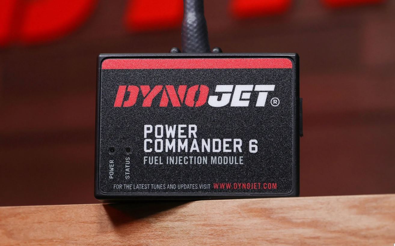
PC-6/AT300/GTM 5AM/7SM ECU Flash Tool
Power Commander 6 w/AutoTune-300 & GTM® ECU Flash Tool Programmer This is a FULLY dynamic system. Includes our GTM Flash Tool with the PC-6 and AutoTune-300 – w/two Bosch wide band 02-sensors to replace the OEM narrow band 02-sensors. Note: The stock fuel system is NOT dynamic/adaptable like...
Chris, I am not accessible direct (PM or email) for questions like this normally, so please don't address me personally here. That said, I'm happy to answer here if I see it. Only product purchase questions can be emailed via the GTM Store. We do not answer tech support questions via email.regarding your recommendation of upgrades in keeping with my airbox removal. I have a couple questions if you dont mind.
Thank you very much. Very informative. The other route I mentioned was in fact putting the stock airbox back in. Knowledge is power and in this case the more I learn the more I realize the importance of going the distance with Todd's kit or reinstalling the airbox. At this time it makes the most sense for me to remain stock. My main focus in removing the airbox was to free up space not to enhance performance but this is more than I bargained forGood morning from the UK.
These forums are a great source of information and ideas, but I don’t want someone reading my post and following the thread without realising the full implications…….
Please bear in mind that any modification to the air box will cause running issues with your Guzzi.
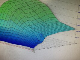
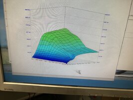
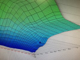
Re -reading my posts I talk about DYNO time and setting my California up….but what was also included in this dyno time and not mentioned was a lot of map adjustment in order to sort out the fuel to air ratios. You can not do this without specialist tools and equipment to access the ECU,...refer to the air ratio images below…each of those grids have to altered, smoothed out and inputted.
This cannot be done by your average guy….me included.
You need dyno time and someone skilled to make the map changes and read the results. I love dyno work and have access to them, but simply removing the air box or changing the exhaust with NO other mapping or fuelling changes will ruin your bike.
GTM offer the out of the box…no need to dyno…a tried and tested fuelling kit set up to your bike…then they monitor the results and tweak to suit. This solution is great if you want to let someone else do all the crazy work and dyno time. …the GTM solution….is just that, an out the box bolt on and ride answer to any changes made to engine set up.
You MUST….look into changing or adjusting your fuelling if any intake or exhaust changes are made.
I am an engineer and happy and relaxed to make changes and monitor…..and the changes are straight forward from my skill set, point of view…but maybe not from yours.
I will give you an example….search out images of an OXY/Acetylene torch on the you tube thing……watch as they adjust the flame with a mix of both gasses…easy…but if they add too much gas…the flame goes all orange and yellow and gets very Smokey. Add to much air and the flame goes white and blue and finally goes POP! That is your combustion chamber….right there…going all sooty or going all white and potentially POP….by all means make your changes …but be aware of being way too rich….or worse…way too lean.
The OEM ECU is not a smart thinker….it will not change the fuelling on its own….its not even really a brain…it’s just a electronic box to sequence events…..also it’s a box that Guzzi changed from 2011 to 2016…..to meet the emission controls of the EU….you will need outside help to make your fuelling changes…and you MUST ……I hope this helps
regards
Gavin
The Scottish Engineer
. Again I really appreciate the technical clarification as although I am a 30 year ase certified automotive technician . My experience has entirely been within the realm of placing stock equipment that is broken back into service as it was originally designed to operate . This effort is entirely different. To live is to learn .... My hat is off to you Gavin for accomplishing this effort and to Todd for his accomplishment and service to the Moto Guzzi community... this did help. regards