• Ciao Guest - You’ve landed at the ultimate Guzzi site. NEW FORUM REGISTRATIONS REQUIRE EMAIL ACTIVATION - CHECK YOUR SPAM FOLDER - Use the CONTACT above if you need help. New to the forum? For all new members, we require ONE post in the Introductions section at the bottom, in order to post in most of the other sections. ALWAYS TRY A SEARCH BEFORE STARTING A NEW TOPIC - Most questions you may have, have likely been already answered. DON'T BE A DRIVE-BY POSTER: As a common courtesy, check back in and reply within 24 hours, or your post will be deleted. Note there's decades of heavily experienced Guzzi professionals on this site, all whom happily give endless amounts of their VALUABLE time for free; BE COURTEOUS AND RESPECTFUL!
  • There is ZERO tolerance on personal attacks and ANY HYPERLINKS to PRODUCT(S) or other competing website(s), including personal pages, social media or other Forums. This ALSO INCLUDES ECU DIAGnostic software, questions and mapping. We work very hard to offer commercially supported products and to keep info relevant here. First offense is a note, second is a warning, third time will get you banned from the site. We don't have the time to chase repeat (and ignorant) offenders. This is NOT a social media platform; It's an ad-free, privately funded website, in small help with user donations. Be sure to see the GTM STORE link above; ALL product purchases help support the site, or you can upgrade your Forum profile or DONATE via the link above.
  • Be sure to see the GTM STORE link also above for our 700+ product inventory, including OEM parts and many of our 100% Made-in-SoCal-USA GTM products and engine kits. In SoCal? Click the SERVICE tab above for the best in service, tires, tuning and installation of our products or custom work, and don't miss our GT MotoCycles® (not) art on the BUILDS tab above. WE'RE HERE ONLINE ONLY - NO PHONE CALLS MADE OR RECEIVED - DO NOT EMAIL AND ASK QUESTIONS OR ASK TO CALL YOU.
  • Like the new V100, GuzziTech is full throttle into the future! We're now running on an all-new server and we've updated our Forum software. The visual differences are obvious, but hopefully you'll notice the super-fast speed. If you notice any glitches or have any issues, please post on the Site Support section at the bottom. If you haven't yet, please upgrade your account which is covered in the Site Support section or via the DONATE tab above, which gives you full site access including the DOWNLOADS section. We really appreciate every $ and your support to keep this site ad-free. Create an account, sign in, upgrade your account, and enjoy. See you on the road in 2024.

crank oil seal -- DIY time and what parts?

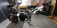
Started working on the beast. Pretty easy going so far, was a bit of a head scratcher with all the little silly bolts to remove the front fairing but the rest was very easy. Now on to disconnect all the engine accessories and liberate the lump from the frame.

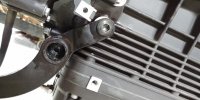
I'm guessing I'd have to look into removing the silly evap canister while I have it this far apart. Anything else that is a known issue or an easy upgrade?

20180811_230434-jpg.15406
 

Attachments

  • 20180811_230434.jpg
    20180811_230434.jpg
    112.7 KB · Views: 101
The two bolts holding the right side center stand bracket to the block are frozen solid :/ Heated them up real good and put some penetrating oil on, but by the looks of it will have to drill 'em buggers out :/

From what I can tell, if say I drill just the front one out, I can still separate the gearbox from the block so probably will do that and leave the other one alone.

20180812_153532-jpg.15407
 

Attachments

  • 20180812_153532.jpg
    20180812_153532.jpg
    100.4 KB · Views: 101
Also, the alternator lead, what a bugger! Looks like it's not metric, or maybe 9mm (???wtf), and no access. Would take a flex head ratchet wrench to remove, but it's neither 8 or 10 and I don't have standard or 8. Double bugger!
 
Got the alternator lead handled, it's a 10mm just that the wire plate is bent in a shape that wasn't allowing my flex head wrench good purchase. All ready for engine removal, I think. Might have to ask a little help with the vent hose routing, I didn't label them well enough since I thought they'd just stay in place but once enough stuff got removed they are now all over the place :)
 
Lump out of the frame.. Now to deal with stuck bolts on the damn bracket.

Silly question, do I have to just separate the clutch housing from the crank case or I have to get the transmission off first?
 
Lump out of the frame.. Now to deal with stuck bolts on the damn bracket.

Silly question, do I have to just separate the clutch housing from the crank case or I have to get the transmission off first?

Remove the gearbox as a unit. Just unbolt from the engine block. Look at a parts manual. If you separate the clutch housing first you will have gears all over the place.
 
Yes, a few bolts & nuts, trans comes off. Clutch is not under lots of pressure like 2 plate. There is a shop manual in the Resource section if you need one.
 
Thanks for the advice guys. Got the dang bracket unbolted without having to drill anything out, looks like penetrating oil did its job. Motor is on the stand ready to go. I got the jb-welded transmission oil drain plug out and looking at Timesert that will go in there and the thickness of aluminum case there, looks to me if I just use Timesert how instruction tells me, it will have 2 issues: won't allow fully draining oil (and getting metal flakes out) because timesert will stick out on the inside, and second the part of the insert that is supposed to expand isn't actually going to be inside the tranny case so it won't have any purchase on the cases. So I'm thinking cutting the timesert to length and using red locktite or jbweld to keep it there.


jiZcrv0XMMtLo0vevZGHQveP9ntKMX3LepSytOk8ZpA09EUTP49E8tS8rLlxt9TI3AMAw1Rp0EpEWofQ4UOPwnqdkd8uYdH1xhg3-iRZ4IoBe-bD66z0KTQMhB09D_gEmUGglK9HvhjOgoAZNU1YOxR5QfhUzoxDnzZd6lDHdzbQxEczpwyz7u-J0RdiqxkmHY1LoEpEnNNoFhRj03EWIIqztYeqbEr4l6ORsN2bq0fax1jeZ_cjA9bpSKeaMAXx9uZ9TWBxbjKGlKvrLRHBw0hDnLtkTuT4mk-n2VMWIJdA6Wa7Csa7-gI-QjF8_v_Ny-TM_mmpwb_WtfwPf9mgycyW8NTffKoLPIk6i8p0iy8F8RoYBCA_RxSoBOMsNu-CkdOaT2nirTi_-rGxZIPKvQE-RKa744VOfuEkbbVh6yg3z1U7XhOKPqa-Duxwhg-RDrVeyeCxGvGUQg-fM508Vpwp5lvhtLcd7csG0q4ZYAu8mgu8IUaRjUAx2JRAeBu5RA1uwq593xfiXvyBEaL7-_WFkvyuGcyEAYAsE7Zdo9QY_F22NwaGKGeM_C7HKvYFuYbPLP0c-yhrk1fFRbd6Q6vVpK3qkAfk4u85UOmL=w1510-h755-no
 
Thanks for the advice guys. Got the dang bracket unbolted without having to drill anything out, looks like penetrating oil did its job. Motor is on the stand ready to go. I got the jb-welded transmission oil drain plug out and looking at Timesert that will go in there and the thickness of aluminum case there, looks to me if I just use Timesert how instruction tells me, it will have 2 issues: won't allow fully draining oil (and getting metal flakes out) because timesert will stick out on the inside, and second the part of the insert that is supposed to expand isn't actually going to be inside the tranny case so it won't have any purchase on the cases. So I'm thinking cutting the timesert to length and using red locktite or jbweld to keep it there.

You might try just using a helicoil. They come in different lengths and you can file off what remains on the outside. You will still have the problem of metal filings, but if you grease your drill bit and tap then flush the case before putting in the helicoil you may be successful. Measure the thickness of the case and mark the helicoil for where to stop inserting. Knocking the tab off might be a little tricky but it may be possible to remove with needle nose pliers.
 
Yes bolts that hold the main bearing carrier were 25mm instead of 20mm on this one, and the gap between the bolt head and the surface of the case is 9.5mm when the bolt is bottomed out, bulletin says it should be 8mm or less. All but one bolt were almost finger tight, took very little torque to get them moving. Also the joint with a dowel pin and an o-ring on the flange had a slightly bent dowel pin, a scratch from obviously trying to force the carrier on while it wasn't aligned right (initial assembly I'm sure), and I have the o-ring recess measuring 1mm instead of 1.5mm the service bulletin is talking about.

I am totally lost with the clutch situation. I didn't use any special tools to take anything apart, just backed out the 6 bolts that hold the thing together in steps trying to keep them even. I didn't ever see a dry clutch before and the manual didn't mention anything special, just says "remove the bell and friction disc".

Now putting it together, I see the manual mentions a special tool to align the pressure plate, Ok I can align that one just fine with a caliper. What kind of "reference" are they talking about for the "clutch disc"? It's free floating anyway so it just needs to be close enough isn't it? Then it says "place the friction disc, center it" (they spelled it "centre" actually). Then they say to just bolt the bell down operating the bolts evenly.

So turns out the special tool I paid $80 for plus shipping is for some other clutch design and is useless here. Centering the pressure plate seems I can handle just fine without any special tools. If I don't center the friction disc right, I simply won't be able to mate transmission to the bell housing. So, no special tools?

Other than that, I did get the loctite they ask to replace the gasket with, and I'll go ahead and do that. Really debating what to do with the o-ring and the oil passage. I don't think it was leaking from there, it was likely the gasket. I'm surprised about them asking to INCREASE the space for the o-ring by .5mm. Maybe the tension that the o-ring was creating directed towards splitting the main bearing carrier flange and the crank case is what they think can contribute to an oil leak, so they want more space for the o-ring to reduce the pressure? I could just not put a new o-ring there and reuse the old one, it's plenty squeezed already.


So currently it looks like I'm gong to replace the main seal and the o-ring, use shorter bolts and just put it all back together without using any special tools. Machining the recess for the o-ring seems a good to have but I have my doubts it fixes anything.
 
Last edited:
This is the correct centering tool http://www.harpermoto.com/?subcats=...erformed=Y&q=020672Y&dispatch=products.search I can't seem to find a picture for it. Guzzi part number is 020672Y which is different from the 5 speed tool. A possible technique for centering the clutch plate is to not tighten down the clutch cap. Use the gearbox to center the clutch plate, then remove it and tighten down the clutch The service manual has a good picture of the tool and it is large.

Do not re-use the o-ring. Do take the flange to a machine shop and have the groove increased by 0.5mm.
 
Yeah, now that I slept over it, if I'm removing the gasket it makes the space for the o-ring even tighter so makes sense. Removing the gasket kind of does't make sense, maybe they wanted something that will actively bond this thing to the cases.

Thanks for setting me straight and yes makes sense what you suggest to center the clutch like you suggest.
 
One more strange thing: I now have 3 different o-rings: original, the one sent by MotoI and I also bought a Honda part that is the same diameter but is supposed to be a bit thicker. Original is 2mm thick like I expected. Honda part is 2.3mm like I expected. What MotoI sent is 2.5mm thick, visibly bigger then either of the other ones.

I made this crude tool from a simple bolt to hog out the space for the o-ring (I really just want to get on with riding the darn thing, not wait for machine shop people to get to it!), and it worked pretty Ok. Given all the nonsense with the o-rings I did about 1.8mm instead of 1.5, the o-ring that MotoI sent still sticks out quite a lot. If the original was 1mm deep and a 2mm thick o-ring, now I have 2.5mm o-ring and they want 1.5mm depth. That's still 1mm of o-ring sticking out. Sure more of it to squeeze but I don't like this math.

Will doze the darn thing with gasket maker on top of the o-ring and put it back together.

Left to right what MotoI sent, Honda part, original.

I think MotoI messed up on my order, it was part 874980 that clearly states it's 2mm elsewhere.
http://www.motointernational.com/store//seal-ring-o-ring-72171


T7AZbzIDZw1r5BwKYxuFNKdzc21hGCHg-DFM-m-_2z68if3jThoifhmpCCZM6j-xyYZ7tDWqAO2WQWSQ82K2px568saCR83FqSvWq3z3fLqksB7pfrcCadQH2QPGH3Pj_4obBKi7vB8w8PCYZodAkysisOoUtKQAcxpdRFgsNP0NB90CK6gWNrWdIDVqMJeW5Dr7dpA7y8-ybn8zBVqm2vNxRT1l-6GdoSlrBZdvd4nBfc7ml62RPBKwqIgXkgBaCc3ztDXRcYch61FjZEZZUFjnm2vc2c1FdPCzzhaFQrDQqR1VV87FXVZL6pewQwaBdci9ivTQnLIaJEcRRTohPaicGMfWIv0SaevO4MJr9TGOn_jdEoiLWRN0z_IhHlrnrOcgUJIgPnaEKrWV8cjhovVWl4jXunRes_qDw4Gh_5CZsZfKuigalD0hdm_iF2U8JU4BHkKxUXZGll4y1ZMbq7ciCgj5axSf78Qit9CikP6jfeFgjOUM7A4n0hcuHb374U_7lHKwMVfDeiIPfrUOorEwwy3vdEg0BlZpZYbQ8ez1MPIoAJ7O8qROOJvdJuwXAKUzjwRJrDanw1UaP36YtUTp4b7ka2ECLbehuWko=w1600-h800-no


X6ZSgsMLbZrfteT95XMCHamzqqKkqUT5UjJ8R60HprITcyQFqup81VfR0C9wGVrITHHcEwrMCShZcHHc2bqGX3BwkPGUqzNNWHjVPZBvBxl4DfCiXue0FOeUQda9SNWVA136gEMnN97NPX000M8bq9yHH7WzVH_-fds5tfcxzs0XZKHlnmBMLLrS6PfncXvhYZZbnoWGS3m_JvmNxlbWn_gs3ih_XSIBN_Ck4ayKg6c3oWo4uC1e5Qs90dLEzb28J9tuMTMHE6TVY-qKEIGml4aUva6MfjRi-ErQTVI5XFDwjUDkWj8_GMnDEQZCVtQH5etcfA34THowwVwU-PJeuBJHcHEi5abim1_8Z2MMGnnEEnn48fnpSvQArhjBHtwutodJLVi8ctqz11bSAQW4HH8kva5B2LEQUhy5OK5cXgXMHyYwRSLPLmn4XWutPXnGRes028vWRO2Y-y_MKBLAufxC7XcfpSuwCeJ2Y5AjHwFNWHnygfjZr2rD_gWEUrBRlfuF9AZMj9m9ny8aEbiagzq_TXZbNBqOToa-Gt2Bqp-dsWjhNMPsQRDDXnrMhzHQYzOuj1td44C3w-F9-MKuupPPK4g3XFejEOahQc0L=w402-h804-no
 
Last edited:
I hope you left a very smooth finish in the groove with that home made tool. Any imperfections and you will be inviting a leak.
 
Finally got a few evenings to assemble everything back together. I didn't get a smooth finish with the crude tool of course but decided it's good enough. Cut out a ring of sandpaper and cleaned up the bottom of the "well" with that using the same "tool".

Looking at the o-ring setup I'm fairly convinced that the issue causing the oil leak is that the old o-ring is simply too weak (thin) and paper gasket is not strong enough to hold the oil pressure in when the o-ring isn't quite doing its job either. It wasn't the bolt length since the paper gasket was pressed in there pretty good, took a long time to clean the flange surfaces up real good.

So the factory solution is to use a thicker o-ring with a deeper groove for it in the flange, plus use flange sealant instead of a paper gasket so if o-ring does leak a little, the sealant would still hold the oil pressure and not allow a leak to happen.

I got the whole o-ring space filled with gasket maker as well so between the bigger o-ring, gasket maker and flange sealant seems that's the best bet to not have that leak happen again.

20180901 141131 HDR 20180901 141145 HDR
 
Of course I have one bolt left behind which I'll have to find where is it coming from, the darn tank cover parts won't line up to not have a gap in the most visible place no matter how I try, turns out the battery is old and won't hold good charge, and a few other things I discovered that will need to be addressed.

Plus, now the low and high beam won't work, except for when the beam switch is in a "flick the high beam" position, then the high beam turns on just fine. On to chase down what did I not connect right or if the relays are bust.

Oh, and despite all my best efforts I did manage to re-tap the stripped oil drain crooked so had to spend quite a bit of time filing the darn thing square, by hand. It worked Ok though, no leaks.

Overall:
1. No special tools used. Clutch was no problem, just line everything up to be centered and it's a piece of cake
2. Hanging the bike from rafters worked Ok. Even stuffed the motor back in solo, was a b1tch but I got it done no problem
3. Except for the fairings the bike is pretty easy to work on, everything is simple and straightforward, just different from what I'm used to
4. I hope whoever designed the upper fairing mounting system lives a long and prosperous life but did not design anything else after that
5. I still can't figure out how to turn the heated grips on lol.
 
Whew, headlight issue was just a blown fuse. I'm suspect how is that a 40A fuse got blown.. Maybe battery voltage got low and it happened. I don't even have a 40A to replace it with, put 30A in and seems to hold up.
 
Whew, headlight issue was just a blown fuse. I'm suspect how is that a 40A fuse got blown.. Maybe battery voltage got low and it happened. I don't even have a 40A to replace it with, put 30A in and seems to hold up.

I recommend you pick some up at an auto parts store. A 40 is specified for a reason.
 
Back
Top