• Ciao Guest - You’ve landed at the ultimate Guzzi site. NEW FORUM REGISTRATIONS REQUIRE EMAIL ACTIVATION - CHECK YOUR SPAM FOLDER - Use the CONTACT above if you need help. New to the forum? For all new members, we require ONE post in the Introductions section at the bottom, in order to post in most of the other sections. ALWAYS TRY A SEARCH BEFORE STARTING A NEW TOPIC - Most questions you may have, have likely been already answered. DON'T BE A DRIVE-BY POSTER: As a common courtesy, check back in and reply within 24 hours, or your post will be deleted. Note there's decades of heavily experienced Guzzi professionals on this site, all whom happily give endless amounts of their VALUABLE time for free; BE COURTEOUS AND RESPECTFUL!
  • There is ZERO tolerance on personal attacks and ANY HYPERLINKS to PRODUCT(S) or other competing website(s), including personal pages, social media or other Forums. This ALSO INCLUDES ECU DIAGnostic software, questions and mapping. We work very hard to offer commercially supported products and to keep info relevant here. First offense is a note, second is a warning, third time will get you banned from the site. We don't have the time to chase repeat (and ignorant) offenders. This is NOT a social media platform; It's an ad-free, privately funded website, in small help with user donations. Be sure to see the GTM STORE link above; ALL product purchases help support the site, or you can upgrade your Forum profile or DONATE via the link above.
  • Be sure to see the GTM STORE link also above for our 700+ product inventory, including OEM parts and many of our 100% Made-in-SoCal-USA GTM products and engine kits. In SoCal? Click the SERVICE tab above for the best in service, tires, tuning and installation of our products or custom work, and don't miss our GT MotoCycles® (not) art on the BUILDS tab above. WE'RE HERE ONLINE ONLY - NO PHONE CALLS MADE OR RECEIVED - DO NOT EMAIL AND ASK QUESTIONS OR ASK TO CALL YOU.
  • Like the new V100, GuzziTech is full throttle into the future! We're now running on an all-new server and we've updated our Forum software. The visual differences are obvious, but hopefully you'll notice the super-fast speed. If you notice any glitches or have any issues, please post on the Site Support section at the bottom. If you haven't yet, please upgrade your account which is covered in the Site Support section or via the DONATE tab above, which gives you full site access including the DOWNLOADS section. We really appreciate every $ and your support to keep this site ad-free. Create an account, sign in, upgrade your account, and enjoy. See you on the road in 2024.

Floating rear caliper

guzzimike

Cruisin' Guzzisti
Joined
Oct 28, 2008
Messages
103
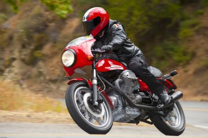
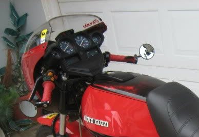
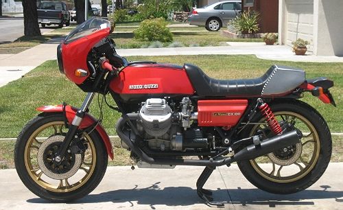
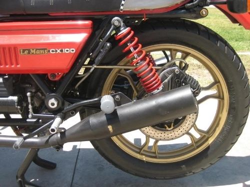
I have a 1979 CX100 Le Mans, which I have "customized" over the past18 years. Items include lightened flywheel, SS brake lines, Agostini Timing Gears, Ago Rear Sets, Stucchi saddle, Marauder Fairing , Malossi velocity stacks, Tomaselli Throttle, etc..

But my latest, mostest customization was a Floating Rear Brake Caliper and Torque Rod DIY retrofit. .

The reason for this modification was that I was experiencing a lot of Rear Wheel Hop when brakeing hard down from "vigorous" speeds; and this led to both increased Braking distances and also it definitely upset the stability of the frame, which in turn increased "Pucker Factor".

By retrofitting this Floating Rear Caliper / Torque Rod system, the same brakeing forces still exist; but are now distributed over a larger area of the frame so their overall effect is much minimized ( Think: showshoes for walking on deep powder without sinking )

This modification removed the fixed position of the Brake Caliper on the swingarm and instead allows the caliper to rotate unencumbered around the rear Axle, supported by the Torque Rod. This places the Rear Brake Caliper in a flexible trapezoid, relative to the road surface..

So, whereas the original rear brake caliper pivoted in an arc with its fulcrum being the Swingarm Bolt, it now moves in a more linear, Up & Down manner.

IOW, where before the negative brakeing forces were absorbed only by the Rear Shock, Rear wheel Axle and the Swingarm's front Bolt; these existing forces are now removed largely from the Rear Wheel axle, and are distributed into the fame, near the Battery tray, in addition to being directed onto their original Rear Shocks and Swingarm Bolt locations.


The Torque Rod serves to hold the Rear Brake Caliper in relative place and transmits felt forces onto the frame. The Torque Rod has Heim Joints at both ends for an almost infinite attitude at time of Brakeing. The Rod also parallels the rear Disk, so all forces are in line and rear pad wear is equalized.


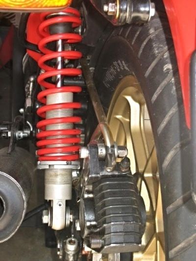
I sourced the Torque Rod and Heim Joints from parts used for steering mechanisms as found on professional Racing Go-Karts sites, so the integrity of both the torque Rod and the Heim Joints under severe stress loads is both Solid and Proven

Bottom line is that now there is No Wheel Hop, and the slowdown is just as hard, but linear and completely smooth; and it is reflected directly onto the frame.

Here are some pics.


Hi

A neat modification, I've thought of doing something similar to my SP1000. Where on the frame did you attach the torque rod? Did you cut the section with the holding tab off the caliper bracket? Di you put any put any sort of bush or bearing in the caliper bracket?

Thanks.

Tony
 
Hi

A neat modification, I've thought of doing something similar to my SP1000. Where on the frame did you attach the torque rod? Did you cut the section with the holding tab off the caliper bracket? Di you put any put any sort of bush or bearing in the caliper bracket?

Thanks.

Tony


Hi, Tony. I attached the front Heim Joint ( Torque Rod ) onto a bracket I made myself. The bracket is bolted onto the Battery Tray, close to the rear crossmember horizontal bar. I did have to make a square cutout ( on 3 sides - I left the top part intact ) on the splash guard to allow for the rod to penetrate and also have UP / Down movement. I left enough material to actr as a "Doggie door". It works fine and I do not get any noticeable debris. I do have an AGM Battery, so extra room in the Battery compartment was available. If I were running Lawn Tractor battery, the Torque Rod modification most likely would not fit there.

On the Caliper Bracket, I kept my original, but bought a spare one from MG Classics, and cut off the holding tab.

Here's a pic:


Also, I did have to increase the diameter of the Axle port in this rear Caliper Bracket.

This was necessary, because the Rear Caliper Bracket originally doubles also as a Rear Wheel spacer, fitting between the left side of the wheel-bearing and the Swing-arm.

In order to make for Free Floating Bracket, we have to isolate it completely from both the wheel and the swingarm .

In order to do this, I had to fit TWO bushings within the newly modified ( ported ) Caliper Bracket; and in addition, I had to take off about 1mm from the width on this Caliper Bracket. But let's take this in order of modification...

I used bronze / copper bushings for these purposes. I got the bushings at my local ACE Hardware supply. I cannot recall the exact diameters, but what I did was to take the rear axle with me to the hardware store.

First, I found a bushing with an inner diameter which fit snuggly around the axle ( let's call it bushing BA ).,

Bushing BA's length must be identical to what the width was on the original Caliper Bracket. Remember bushing BA's main purpose, which is to function as the New Rear Wheel Spacer.

Then, I fond another bushing ( bushing BB ) which fit snuggly, yet rotated freely around BA.

Next, I took the aluminum Caliper bracket and hollowed out the existing axle bearing port so that bushing BB fit tightly within it.

Bushing BB has the same width as the newly modified rear Caliper Bracket ( IIRC, the new width was 25mm )

Note that BB is about 1- 2 mm shorter than BA

OK, so now the Innermost bushing ( BA )funtions as a "new" Rear Wheel Spacer; the center bushing ( BB )acts as a Caliper Bearing bearing, which allows the Caliper Braket to rotate freely around both BA and the Axle..

Well, "rotate freely" is a relative term, as this Free Travel of the Caliper Bracket is limited effectively by the torque rod.

The torque rod's rear heim joint bolts onto an existing hole in the Rear Caliper bracket.

Because the Heim Joints allow for rotational movement around the bolt, make sure that the bolts are torqued down appropriately.

When the system is not in compression, the torque Rod should have some degree of free rotational movement when you "roll it" back and forth between you index finger and thumb. I did this with my bike supported by its Center Stand.

If the Torque Rod does not rotate freely enough, you may have undue friction somewhere in the torque arm; either by rubbing against the rear tire or near where the Heim joints are landed, or it may be a bit of both.

On my bike, I did have to bend the Torque Rod outward a very minimal amount in order to clear the left side of my rear tire.

BTW, I have a 120 /18 rear tire, so it's a bit wider than stock on our bikes, which I think is a 110 / 18.


Well, I hope that this convoluted explanation has helped. It really is easy once you have the parts all laid out in front of you.

I will recommend that you get a spare Rear Caliper Bracket and save your original, just in case that you want to to reverse the modification..I have seen these brackets on Ebay go for about $35.00

Good luck to you.


PS -You do not need to modify the rear Brake line at all.

DO KEEP IN MIND that it is very important to route the Torque Rod so that it is as close as possible on the same plane as the Rear Brake Disk. This will minimize uneven brake Pad wear as well as unnecessary side-loads on the system. Keep it linear.

The picture below shows this Torque Rod to Rear Disk relationship, as well as the slight "bowing" on the Torque Rod which was needed to clear the rear tire:


ca943083-ea28-4297-8e17-100dacde41a5_zps60wu0yjq.jpg


-

-
 
Last edited:
Back
Top