zoom zoom
Tuned and Synch'ed
Getting down to the wire now. ") (Pun intended)
(Pun intended)
In the midst of this install, I have also installed a new Hyperpro rear shock and HP fork springs. I'm looking forward to seeing how this all works out.
Yesterday, (saturday), I spent the entire day working on the front springs and cruise installation. In the interest of neatness, I have shortened or lengthened wires to locate plugs where I wanted. Once I had any wires in their general location, I wraped them in black electrical tape to make my wiring harness. All connections have been soldered and shrink wraped. In cases where I tapped into a wire, such as the coil and brake light, I carefully skined back the insulation, soldered my jumper wire in and applied liquid electrical tape. Once that was dry, I put a layer of "normal" electrical tape over that, and rewraped the harness where I had removed the outer covering to access the wires inside. I used the left hand coil for my pickup. It was easier to remove the coil and get the wire up where I could work with it, rather than any other option. There are still some connections to be made to finalize things, but I finally quit at 10:00PM. I was able to reassemble most of the bike and never needed to remove the main sides or front facia. Here some pics.
In this photo, you see the wire I brought out of the brake wire. I have yet to connect it up. Probably today. The crusie depends on having a path to ground through this wire, (through a bulb), and disengages the cruise when it gets 12 volts thrown at it. There is some speculation as to weather or not it can sense that through an LED. I purchased an automotive relay. The coil of the relay will be from this wire and will trigger the other side to go open, therby breaking the ground connection. (In a normal state, the wire from the cruise sends a few volts through the wire to sense a connection to ground. That is why I felt a relay was the best option.)
Here is the main connector that goes into the servo.
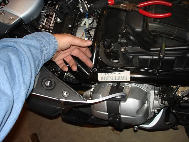
Here is the location I have chosen to mount the control switch. The switch was popped open and NON COROSSIVE RTV was used to waterproof the switch. Thanks Wayne for the RTV heads up. Available at the parts store and marked as such.
This next photo shows the wiring harness from the switch. I joined the grey and red wires before they were put into the plug. The grey wire powers the LED backlight. These both go to a switched 12 volt power source. The ground lead from the switch does not go into the plug. I used spade end connectors for that. I made the length of this batch of wires the same as the wire from the ABS switch. Note: the wires do NOT get plugged into the connector until AFTER they route through the mounting surface.
Since there was a ground wire at the switch and another one off the servo, I chose to make my ground connection up front, using one of the coil mounting bolts. Using a short and long piece of ground wire to eventually supply both ends. The lead from the coil, tapped into the green/orange wire was also laid roughly in place. The remaining wires that connect the switch were put in place, back to front, and all were wrapped into a harness and ty-rapped along the frame with a couple of unrelated wires for stuff I have done.
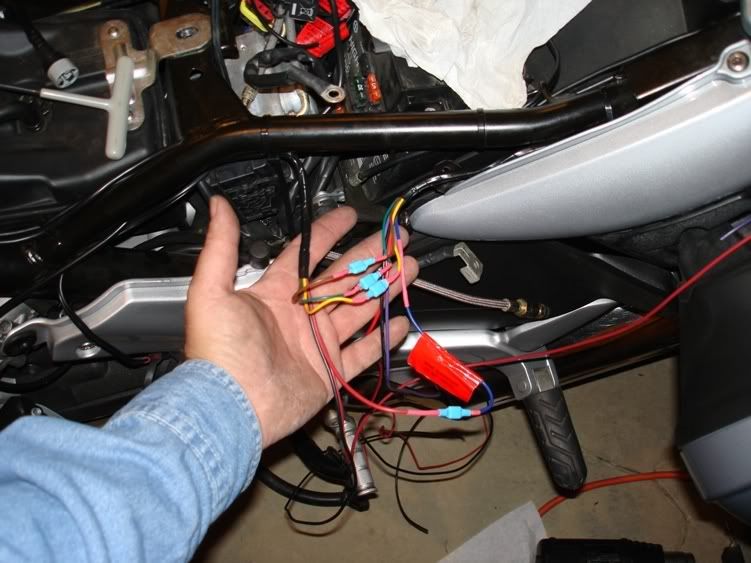
This last photo shows where I joined the front and back harness together. I soldered spade connectors on either end, joined them together and covered them with heat shrink. This gives me an access point should I need it. There is a blue wire coming from the servo that is the coil lead. It has a noise suppressor in it and needs to remain if you alter the wire. Probably, it would be best to locate that device as close to the coil as possible, but I wanted it in an accessable location. So, that is the red piece of paper. you see on the pic. Since I didn't buy wire in every color for what I needed, you see that a couple don't match color wise. If you do that, be sure to tag your wires so you don't get them mixed up.
Zoom Zoom,
John Henry
(Pun intended)In the midst of this install, I have also installed a new Hyperpro rear shock and HP fork springs. I'm looking forward to seeing how this all works out.
Yesterday, (saturday), I spent the entire day working on the front springs and cruise installation. In the interest of neatness, I have shortened or lengthened wires to locate plugs where I wanted. Once I had any wires in their general location, I wraped them in black electrical tape to make my wiring harness. All connections have been soldered and shrink wraped. In cases where I tapped into a wire, such as the coil and brake light, I carefully skined back the insulation, soldered my jumper wire in and applied liquid electrical tape. Once that was dry, I put a layer of "normal" electrical tape over that, and rewraped the harness where I had removed the outer covering to access the wires inside. I used the left hand coil for my pickup. It was easier to remove the coil and get the wire up where I could work with it, rather than any other option. There are still some connections to be made to finalize things, but I finally quit at 10:00PM. I was able to reassemble most of the bike and never needed to remove the main sides or front facia. Here some pics.
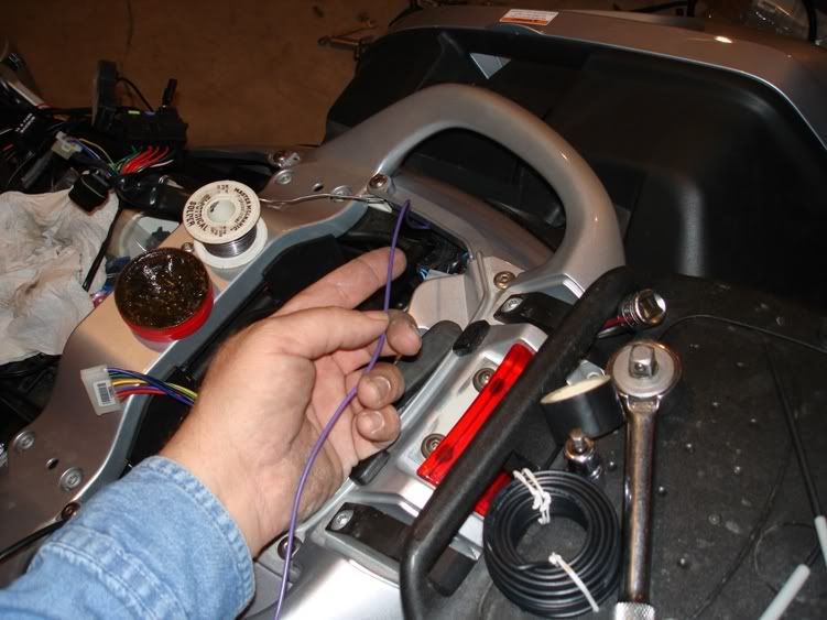
In this photo, you see the wire I brought out of the brake wire. I have yet to connect it up. Probably today. The crusie depends on having a path to ground through this wire, (through a bulb), and disengages the cruise when it gets 12 volts thrown at it. There is some speculation as to weather or not it can sense that through an LED. I purchased an automotive relay. The coil of the relay will be from this wire and will trigger the other side to go open, therby breaking the ground connection. (In a normal state, the wire from the cruise sends a few volts through the wire to sense a connection to ground. That is why I felt a relay was the best option.)
Here is the main connector that goes into the servo.
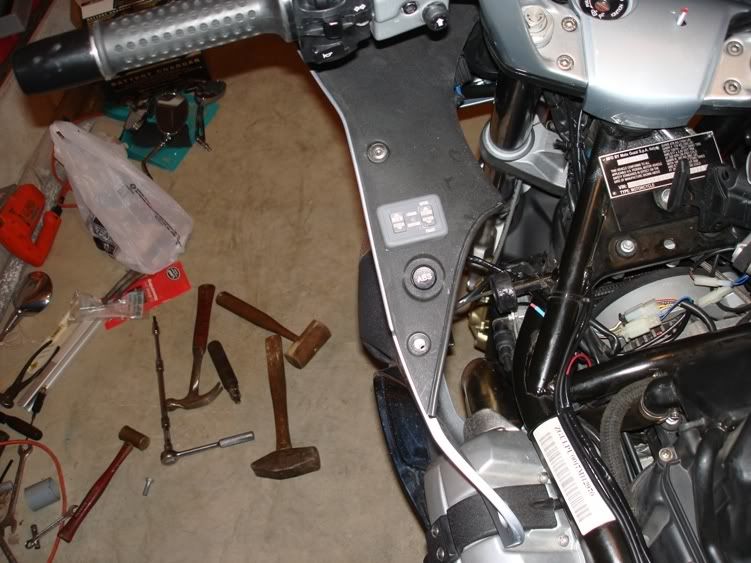
Here is the location I have chosen to mount the control switch. The switch was popped open and NON COROSSIVE RTV was used to waterproof the switch. Thanks Wayne for the RTV heads up. Available at the parts store and marked as such.
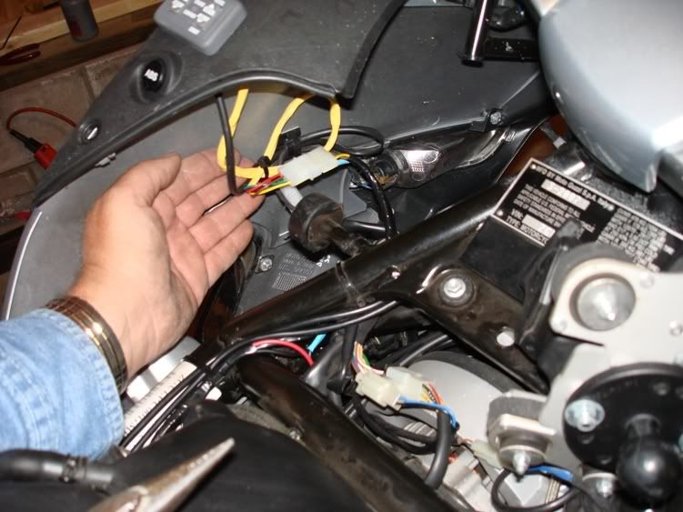
This next photo shows the wiring harness from the switch. I joined the grey and red wires before they were put into the plug. The grey wire powers the LED backlight. These both go to a switched 12 volt power source. The ground lead from the switch does not go into the plug. I used spade end connectors for that. I made the length of this batch of wires the same as the wire from the ABS switch. Note: the wires do NOT get plugged into the connector until AFTER they route through the mounting surface.
Since there was a ground wire at the switch and another one off the servo, I chose to make my ground connection up front, using one of the coil mounting bolts. Using a short and long piece of ground wire to eventually supply both ends. The lead from the coil, tapped into the green/orange wire was also laid roughly in place. The remaining wires that connect the switch were put in place, back to front, and all were wrapped into a harness and ty-rapped along the frame with a couple of unrelated wires for stuff I have done.
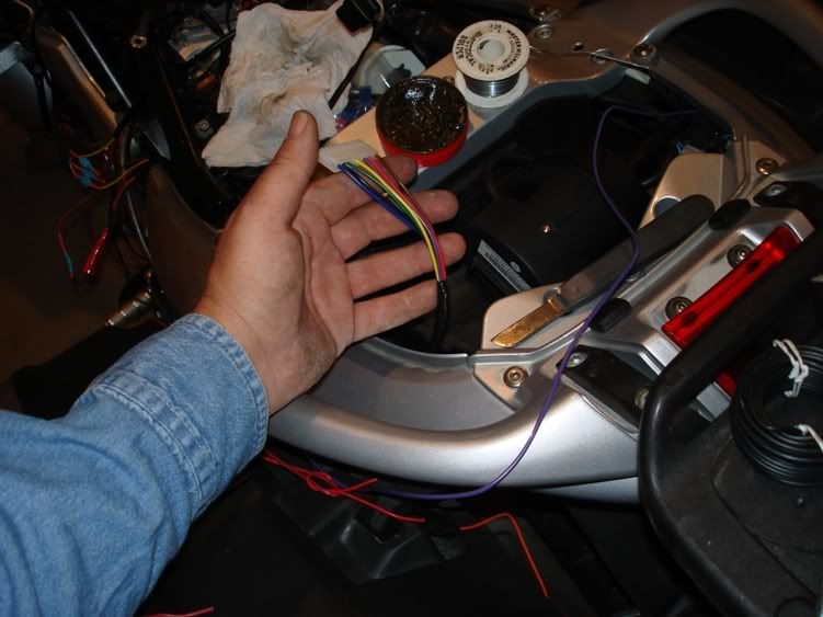
This last photo shows where I joined the front and back harness together. I soldered spade connectors on either end, joined them together and covered them with heat shrink. This gives me an access point should I need it. There is a blue wire coming from the servo that is the coil lead. It has a noise suppressor in it and needs to remain if you alter the wire. Probably, it would be best to locate that device as close to the coil as possible, but I wanted it in an accessable location. So, that is the red piece of paper. you see on the pic. Since I didn't buy wire in every color for what I needed, you see that a couple don't match color wise. If you do that, be sure to tag your wires so you don't get them mixed up.
Zoom Zoom,
John Henry