• Ciao Guest - You’ve landed at the ultimate Guzzi site. NEW FORUM REGISTRATIONS REQUIRE EMAIL ACTIVATION - CHECK YOUR SPAM FOLDER - Use the CONTACT above if you need help. New to the forum? For all new members, we require ONE post in the Introductions section at the bottom, in order to post in most of the other sections. ALWAYS TRY A SEARCH BEFORE STARTING A NEW TOPIC - Most questions you may have, have likely been already answered. DON'T BE A DRIVE-BY POSTER: As a common courtesy, check back in and reply within 24 hours, or your post will be deleted. Note there's decades of heavily experienced Guzzi professionals on this site, all whom happily give endless amounts of their VALUABLE time for free; BE COURTEOUS AND RESPECTFUL!
  • There is ZERO tolerance on personal attacks and ANY HYPERLINKS to PRODUCT(S) or other competing website(s), including personal pages, social media or other Forums. This ALSO INCLUDES ECU DIAGnostic software, questions and mapping. We work very hard to offer commercially supported products and to keep info relevant here. First offense is a note, second is a warning, third time will get you banned from the site. We don't have the time to chase repeat (and ignorant) offenders. This is NOT a social media platform; It's an ad-free, privately funded website, in small help with user donations. Be sure to see the GTM STORE link above; ALL product purchases help support the site, or you can upgrade your Forum profile or DONATE via the link above.
  • Be sure to see the GTM STORE link also above for our 700+ product inventory, including OEM parts and many of our 100% Made-in-SoCal-USA GTM products and engine kits. In SoCal? Click the SERVICE tab above for the best in service, tires, tuning and installation of our products or custom work, and don't miss our GT MotoCycles® (not) art on the BUILDS tab above. WE'RE HERE ONLINE ONLY - NO PHONE CALLS MADE OR RECEIVED - DO NOT EMAIL AND ASK QUESTIONS OR ASK TO CALL YOU.
  • Like the new V100, GuzziTech is full throttle into the future! We're now running on an all-new server and we've updated our Forum software. The visual differences are obvious, but hopefully you'll notice the super-fast speed. If you notice any glitches or have any issues, please post on the Site Support section at the bottom. If you haven't yet, please upgrade your account which is covered in the Site Support section or via the DONATE tab above, which gives you full site access including the DOWNLOADS section. We really appreciate every $ and your support to keep this site ad-free. Create an account, sign in, upgrade your account, and enjoy. See you on the road in 2024.

V7 Classic 2011, install a separate flasher relay

IgorM

Just got it firing!
Joined
Jan 30, 2024
Messages
8
Location
NUTS2 Region Prague, Prague, Czechia
Hello guys

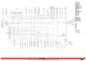
Need an advice here. Considering of changing an OEM dash to something tine and simple. After some investigations of wiring diagram I concluded that the flashers relays are located directly on a dash, so to be able to remove it I need to add some simple relays to the harness. Ideally, a single small flashing relay as is shown on the picture from a wiring manual of a this particular unit. What I face is that I do not have such simple circuits on the bike, but instead from switch I have only two control signals, which go to the dash ("1" and "8" on a diagram) and on the dash I have four outputs to all blinkers (6, 7, 24, 25), positive (23, 26) and negative (14, 23).

Appreciated any thoughts and advice. Thank you guys.


1706631288554
 
Please look carefully at the wiring diagram as I believe you have a partial CanBus.

You could create a nightmare for yourself.
 
Can you elaborate pls a bit, I am not sure I get it
You must search and read. All questions have been well answered here at length. This site isn't a personal assist unless you post in the paid Ask the Wrench section.
 
Can you elaborate pls a bit, I am not sure I get it

 
You must search and read. All questions have been well answered here at length. This site isn't a personal assist unless you post in the paid Ask the Wrench section.
Okay Todd, but I should say it sounds quite gross. I still did not get what I said wrong, if I did - my apologies, english is not my native language. I will spend my time trying to get on well with the way here, but my expectation was that here I can find those people who is keen on sharing the knowledge, and if for the money - so why not? If it not true - let me know I will save your and my time then.

Before answering to Scott I investigated the topic about canbus on the forum as well and read his post which he replied with above also. I still can not get how the post about V7III can help me with my Classic model: neither my wiring diagram has it nor visually I've seen such twisted wiring on my bike during investigations, nor user or workshop manuals have any note about it, but still read through the thread and did not manage to find any more hooks to continue investigation.

Point me out please if you see I am still wrong, I'd be grateful. Otherwise I'd appreciated a normal conversation guys instead this hazing of newbie.
 
Nobody is hazing you.

This is a compendium of knowledge but one must use the SEARCH function to look for and read about topics. If after exhausting your reading skills and you haven’t found what you seek, then a question would be appropriate and most welcome.

Unfortunately as happens many times here, people just pop in and fire off a question looking for somebody to spoon feed then an answer.

That is just not the way this forum works. It would become a bloody mess if it ran that way. There would be redundancy galore.

This is not Social Media and all of this is right at the top of the page in the rotating screens.

I have not looked at your particular wiring diagram for your motorcycle so I cannot confirm if a partial CanBus exists on your motorcycle however if you have a wiring diagram, just look for the sine wave symbol in the wiring. When you see that, if any, is CanBus which is very different from old standard wiring.

Relax, enjoy. Be happy. 👌👍🙏
 
Thx man, I accept and embrace the rules of the forum, I'd be happy if one day I'd be knowledgeable enough to contribute to the common deal. I attached the link to my wiring diagram, but it was removed by the forum rules. I read your previous thread and searched for the corresponding symbols on it, it seems it is not there. So, it leaves me the hope that my bike is old enough not to have a CanBus and I'll be able to finish my idea.

On the scheme the instrument panel is "43". The main question for me now is if I remove it how to wire together so it works properly:
- right turn control signal from switch - R/B (1)
- front right turn indicator - R (24)
- rear right turn indicator - R (25)
- key + input V12 - G (21)
- ground - B (14, 22)
- separate flasher relay which I possibly need to add to the scheme

I think I stuck here due to lack of that domain knowledge. Already went through the docs of 2, 3, 4 and 5 pins relays and their wiring diagrams. All of them use as examples switches of on-off-on type, when OEM V7C looks like different: sending control signals instead of cutting the circuits.
 

Attachments

  • V7Classic_WiringDiagram-1.png
    V7Classic_WiringDiagram-1.png
    214.6 KB · Views: 3
But today I found some interesting thingy which might be a solution for me I think, even though I am not happy it is a bigger than I wanted.

Highsider 2-channels relay

1706649669447

Its manual wiring looks very promising to the problem I am trying to solve
1706649740019
 
Back
Top